How blind fasteners work: every family, step by step
One visual key for every fastener in the catalog, then each family's installation from before to installed. Every step quotes the manufacturer's (or the FAA's or USAF's) own install document and every drawing is traced from that document's figure.
The key
Each part plays the same role in every diagram and always gets the same color and pattern. Learn it once and you can pick out the sleeve, the core, the lock and the formed head on any family, before and after installation. On each family the key also lists the manufacturer's own name for every part, and hovering or focusing a key entry highlights that part in the drawing.
- Sleeve. The tube that goes through the hole. On most blind fasteners its far end becomes the blind head.
- Stem, pin, screw or corebolt. The core that is pulled or turned. On solid rivets and pins this is the whole fastener body.
- Nut or body. The threaded part the screw works against. On Monogram bolts its head is the fastener head.
- Collar. The ring that locks onto a pin, by swaging or by threads.
- Drive and break-off section. Whatever the tool grips and the joint does not keep: pintail, slabbed screw end, drive-nut, driving anvil, shift washer, collar hex. The notch marks the break groove.
- Locking feature. What stops the core backing out: a locking collar, thread-locking feature, swaged grooves or deformed lobes.
- Formed head. The head made during installation: bulb, upset, expanded sleeve, or a solid rivet's shop head.
- Structure, tool side. The sheet the installer works from (the accessible side). Diagonal hatch = metal; ply lines = composite laminate.
- Structure, far side. The other sheet. On a blind fastener this is the blind side, where nobody can reach. Diagonal hatch = metal; ply lines = composite laminate.
- Grip and grip datum. Grip is the total thickness of the stack, measured from the datum: the surface the head bears on. Grip is the dimension you order by.
- Tool and motion. Dashed outline = installation tool (nose piece, pulling head, socket, set, bucking bar). Arrows show pull or torque. Faded parts are leaving the joint.
Reading a sequence
- The drawings are cross-sections through a two-sheet joint. The installer works from the top; the far side is at the bottom. On a blind fastener nobody can reach the bottom, so everything below the stack is formed by the fastener.
- Step with the slider, the arrow buttons or the numbered steps. Keyboard: tab to the slider and use the arrow keys.
- The quote under each step is the document's wording, unedited, with a link to the page. The short step titles are ours.
- Where a source figure has no panel for a step, the drawing holds at the previous panel and says so. Where no public document shows how a family installs, only the installed view is drawn (Cherry 1900 bulbing blind rivet, Jo-Bolt, Hi-Lite).
- Switch the structure between metal and composite to see the joint either way; the fastener is drawn the same. Drawings follow each figure's proportions but are not to scale.
Start with one: CherryMAX
A pulled-stem rivet is the simplest place to start: the stem is pulled, the sleeve bulbs against the blind sheet, a collar locks the stem and the stem breaks off.
Pulled stem / bulbing · 4 steps
1/4Inserted
“The CherryMAX® Rivet is inserted into the prepared hole. The pulling head (installation tool) is slipped over the rivet’s stem. Applying a firm, steady pressure, which seats the rivet head, the installation tool is then actuated.”
Cherry CA-1011 (CherryMAX), p.3, Installation ↗
Drawing traced from: Features figure.
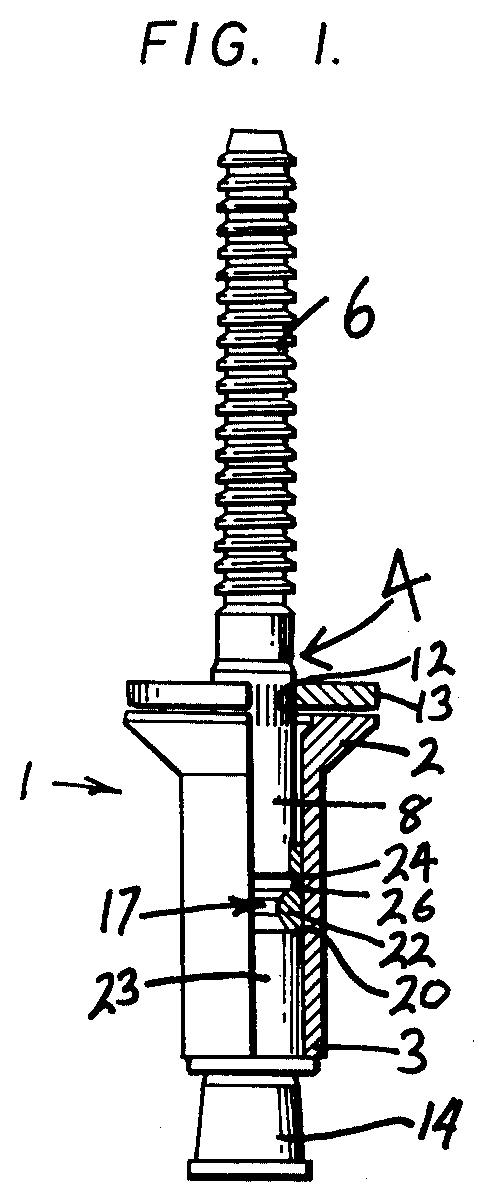
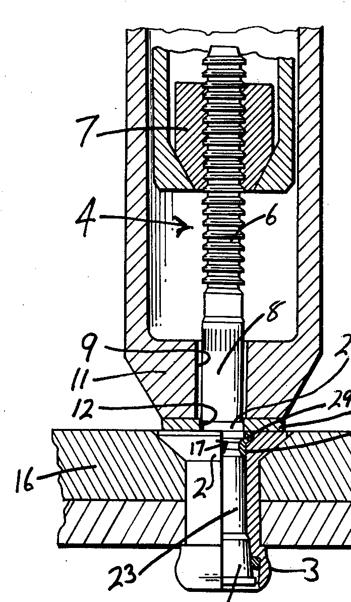
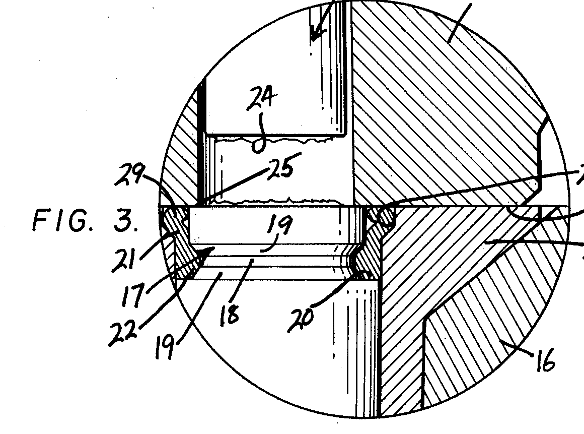
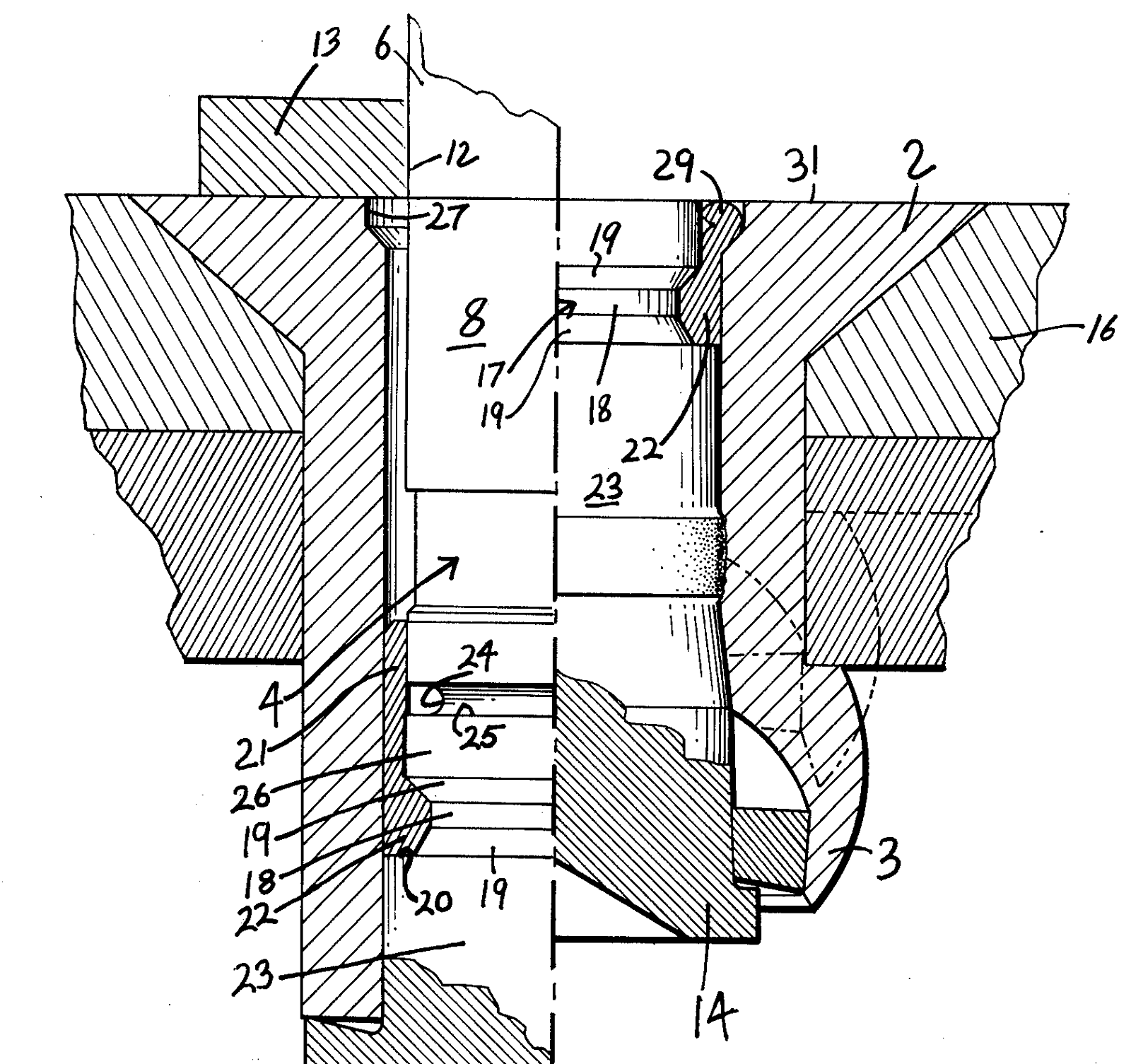
Source images (4): patent and government drawings
A patent drawing shows the patented design, which can differ in detail from today's catalog part. Each image says why it is tied to this family.
Every family, compared
Filter by how the fastener works: pulled stem / bulbing, threaded / torqued, expanding sleeve, pin and collar, solid.
Showing 20 families
Standard blind rivet (NAS1398/NAS1399 wiredraw)generic-NAS
Pulled stem / bulbing · 6 steps
1/6Inserted, sheet gap
“Before pulling begins.”
Cherry CA-1005 (CherryLOCK), p.12, Installation Sequence ↗
Drawing traced from: Panel 1.
CherryMAXCherry
Pulled stem / bulbing · 4 steps
1/4Inserted
“The CherryMAX® Rivet is inserted into the prepared hole. The pulling head (installation tool) is slipped over the rivet’s stem. Applying a firm, steady pressure, which seats the rivet head, the installation tool is then actuated.”
Cherry CA-1011 (CherryMAX), p.3, Installation ↗
Drawing traced from: Features figure.
Source images (4): patent and government drawings
A patent drawing shows the patented design, which can differ in detail from today's catalog part. Each image says why it is tied to this family.
CherryLOCKCherry
Pulled stem / bulbing · 6 steps
1/6Inserted, sheet gap
“Before pulling begins.”
Cherry CA-1005 (CherryLOCK), p.3, Installation Sequence ↗
Drawing traced from: Panel 1.
Cherry SSTCherry
Pulled stem / bulbing · 4 steps
1/4Inserted
“The Cherry SST® Blind Rivet is inserted into the prepared hole. The pulling head (Installation Tool) is slipped over the stem. Applying firm pressure, which seats the rivet head, the installation tool is actuated”
Cherry CA-1037 (Cherry SST), p.4, Installation ↗
Drawing traced from: Panel 1.
Cherry 1900 bulbing blind rivetCherry
Pulled stem / bulbing · installed view
Sequence not shown: no public source for the intermediate stages. Installed view only.
Installed
“BLIND SIDE HEAD MAY BE INSTALLED ON A 5° MAXIMUM SLOPE”
Cherry CA-1035 (Cherry 1900), p.3, CR1919 installed view ↗
Drawing traced from: Installed view.
Composi-Lok IIMonogram
Threaded / torqued · 4 steps
1/4Inserted
“Insert the fastener in the hole. The Composi-Lok® II can be inserted in a properly prepared hole without interference.”
Monogram MBF2003 Rev AG (Composi-Lok II install spec), p.17, §7.2 ↗
Drawing traced from: Figure 15, left.
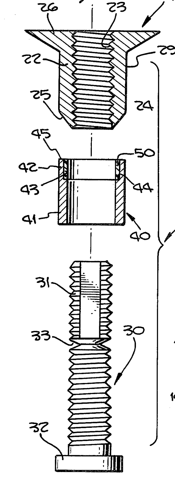
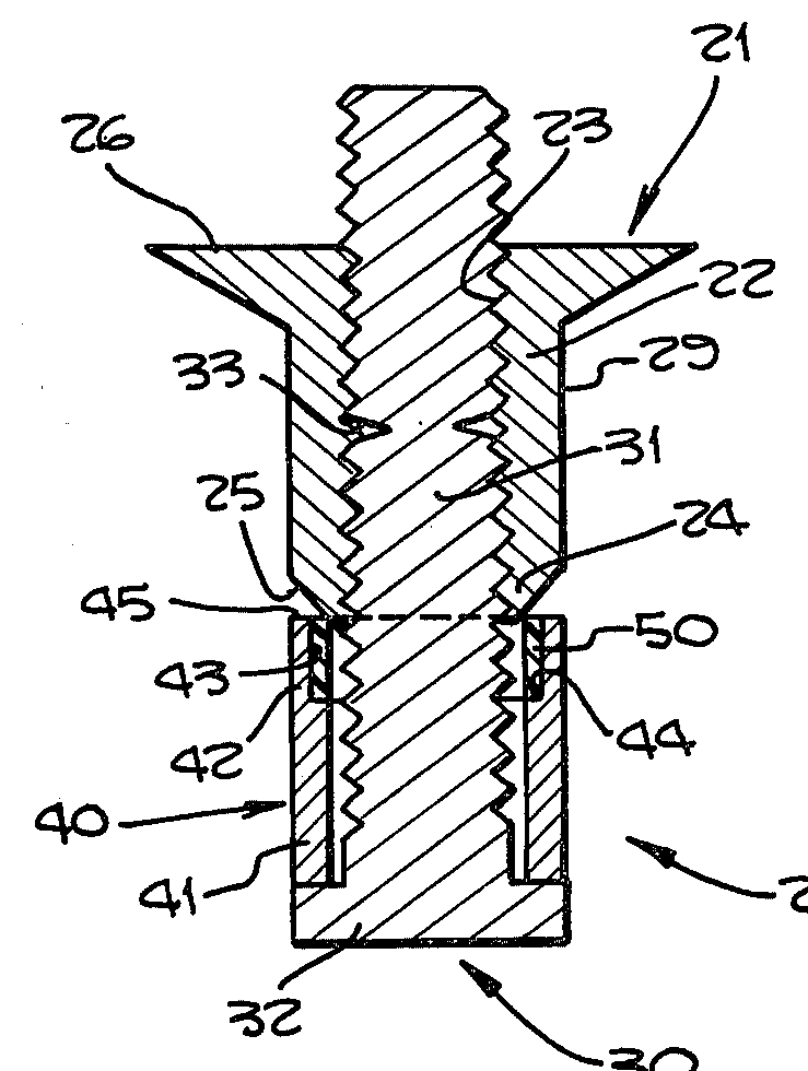
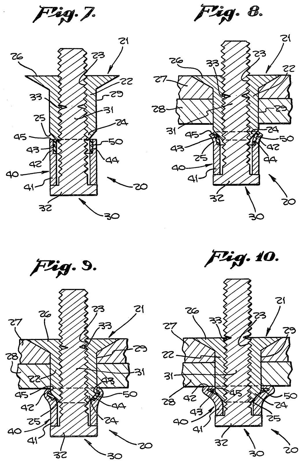
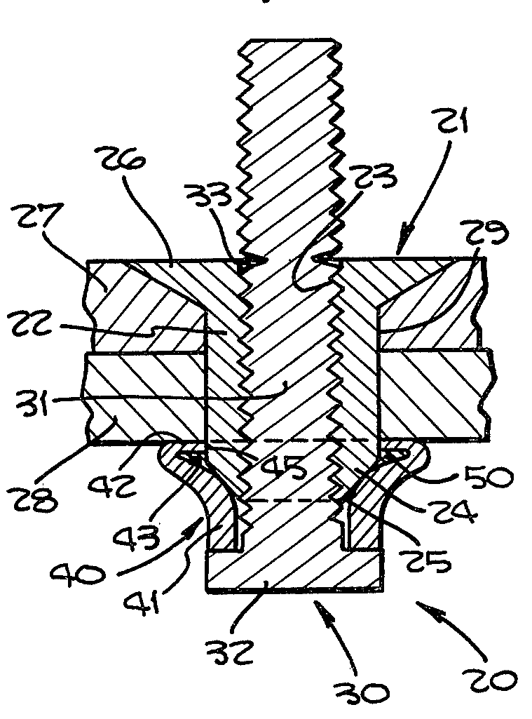
Source images (6): patent and government drawings
A patent drawing shows the patented design, which can differ in detail from today's catalog part. Each image says why it is tied to this family.
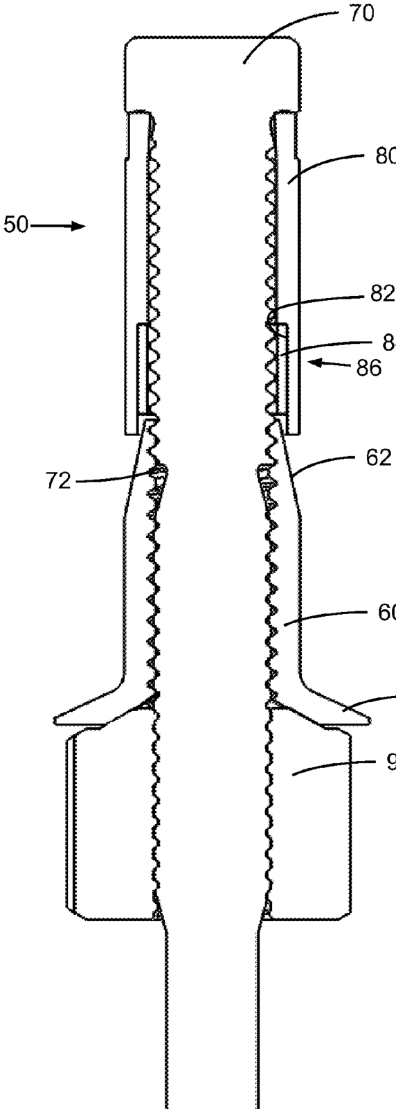
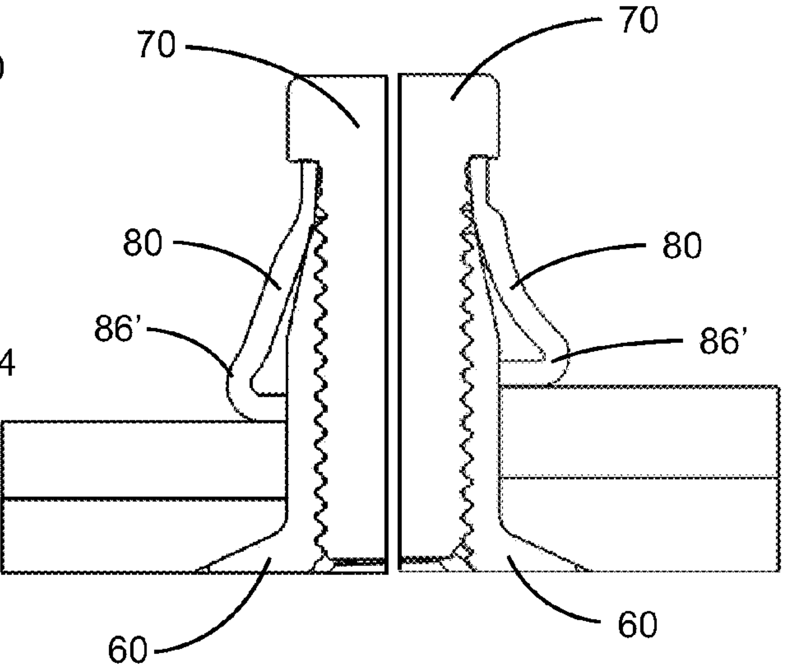
Visu-LokMonogram
Threaded / torqued · 4 steps
1/4Inserted, tool placed
“The Visu-Lok II fastener is inserted into the prepared hole. The installation tool is placed over the screw simultaneously engaging the wrench flats and the DRIVE NUT.”
Monogram Visu-Lok II brochure, p.3, How They Work ↗
Drawing traced from: Panel 1.
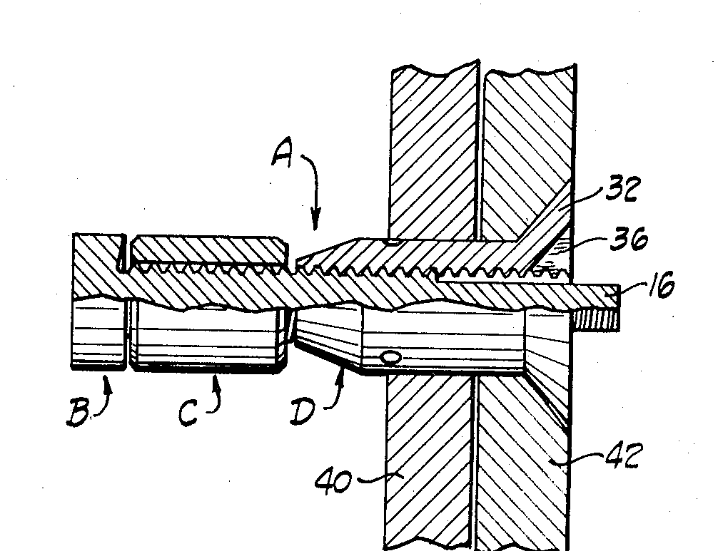
Source images (3): patent and government drawings
A patent drawing shows the patented design, which can differ in detail from today's catalog part. Each image says why it is tied to this family.
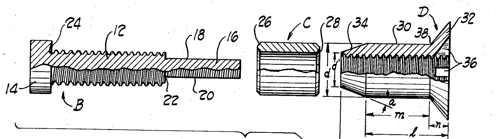
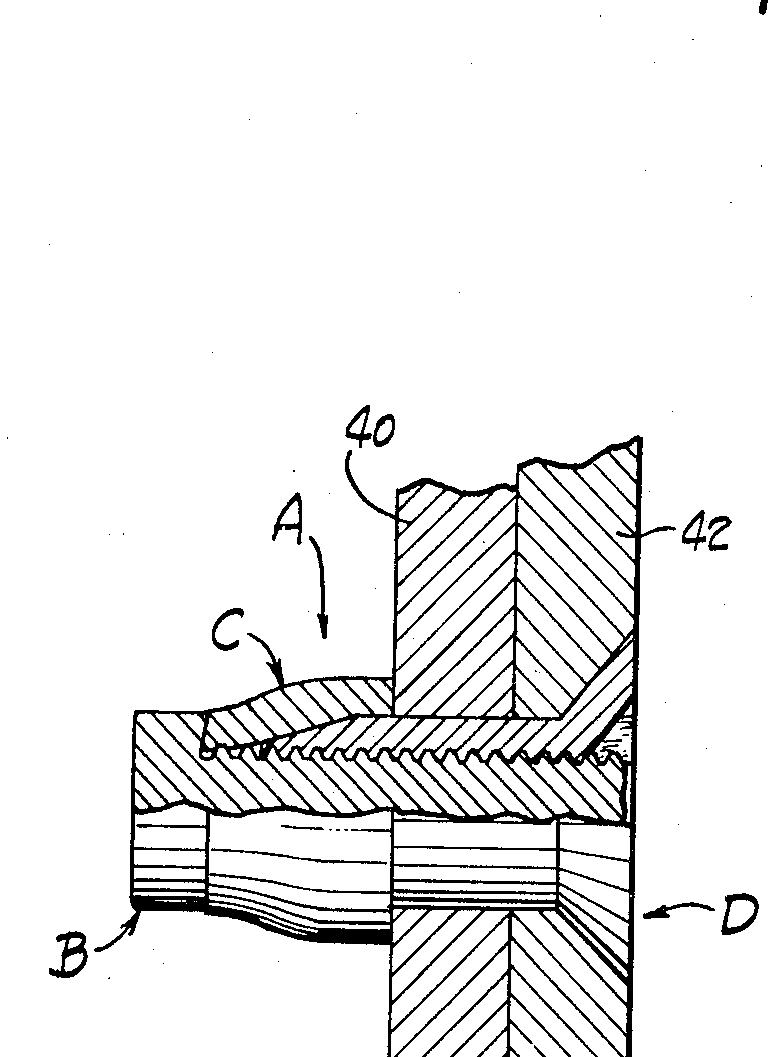
Radial-LokMonogram
Expanding sleeve · 3 steps
1/3Inserted, tool placed
“The Radial-Lok fastener is first inserted into the prepared clearance fit hole. The installation tool is placed over the screw, simultaneously engaging the wrench flats and the DRIVE NUT.”
Monogram Radial-Lok brochure, p.2, Installation Sequence ↗
Drawing traced from: Panel 1.
OSI-BoltMonogram
Threaded / torqued · 3 steps
1/3Inserted, bulbing begins
“The fastener is inserted into the prepared hole. The installation tool is first placed over the flatted corebolt; the nose piece then engages the recesses of the body and installation is facilitated. As the corebolt turns, the nut component travels toward the structure, bearing against the annealed sleeve. This movement forces the sleeve over the tapered nose of the body to begin the initial bulbing action.”
Monogram OSI-Bolt brochure, p.2, Sequence #1 ↗
Drawing traced from: Panel 1.
Source images (3): patent and government drawings
A patent drawing shows the patented design, which can differ in detail from today's catalog part. Each image says why it is tied to this family.
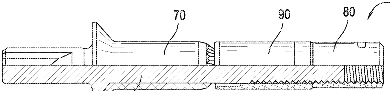
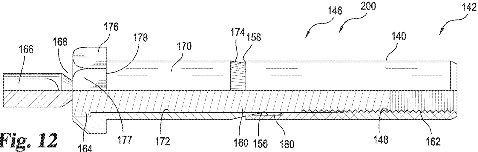
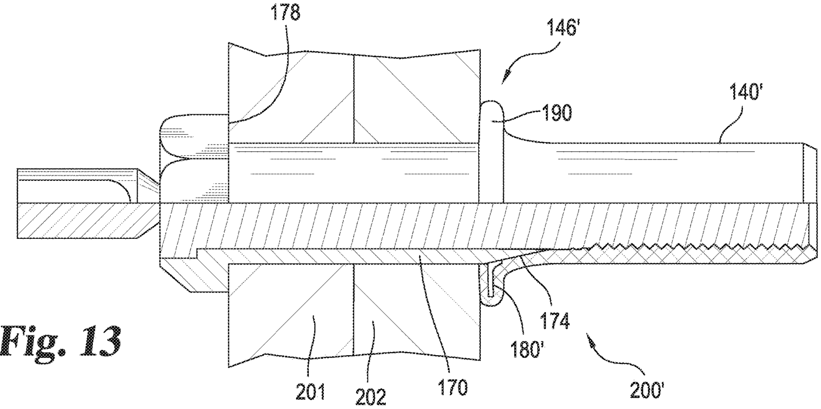
Jo-Boltgeneric-NAS
Threaded / torqued · installed view
Sequence not shown: no public source for the intermediate stages. Installed view only.
Installed
“As the Jo-Bolt is installed, the bolt is turned while the nut is held, causing the sleeve to expand over the end of the nut, forming the blind head and clamping against the work. When driving is complete, the bolt wrenching end breaks off from flush to below the head.”
USAF T.O. 1-1A-8, p.1-84, §1.4.1 ↗
Drawing traced from: NAS1670 installed view.
Install steps, in the document's words (not drawn)
- “Insert Jo-Bolt in the hole. The fastener can be pushed easily into a properly prepared hole and in no case shall fastener be driven forcibly into the hole.” USAF T.O. 1-1A-8, p.1-91, §1.4.8 c ↗
- “Place the nose adapter of the driving tool over the slabbed portion of the bolt shank so that it engages the head of the Jo-Bolt.” USAF T.O. 1-1A-8, p.1-91, §1.4.8 e ↗
- “If the hand gun is used, hold the handle of the tool stationary and turn the ratchet handle. As power is applied, the bolt is turned while the nut is held. The sleeve, compressed between the bolt head and tapered end of the nut, is drawn over the end of the nut and is expanded forming the blind head against the inner surface of the part. When the sleeve is drawing up tight, the slabbed portion of the stem is snapped off completing the driving operation.” USAF T.O. 1-1A-8, p.1-91, §1.4.8 g ↗
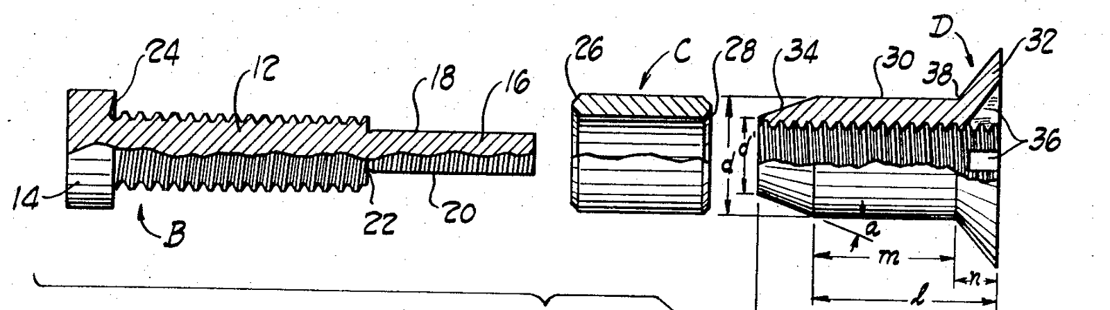
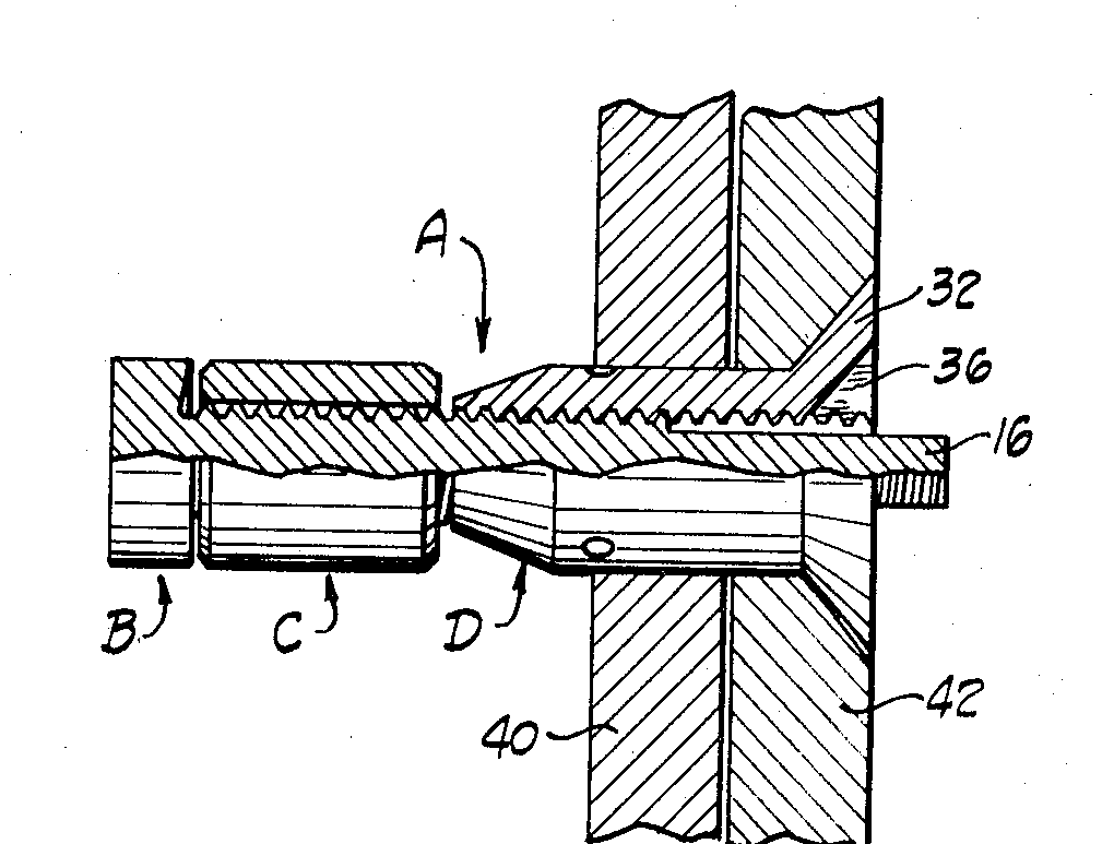
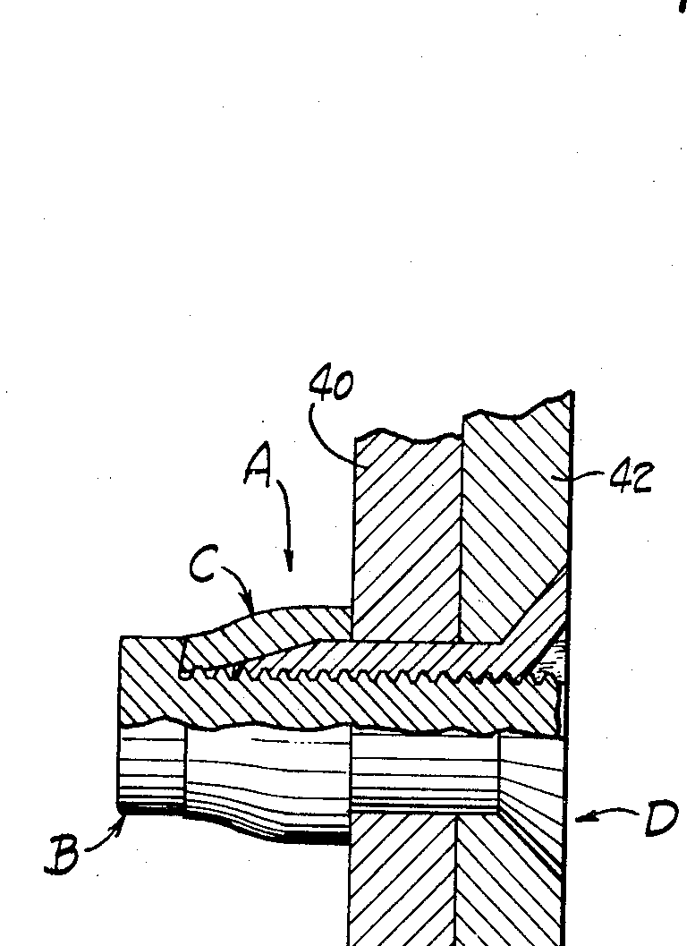
Source images (3): patent and government drawings
A patent drawing shows the patented design, which can differ in detail from today's catalog part. Each image says why it is tied to this family.
Huck BOM (industrial)Howmet/Huck
Pulled stem / bulbing · 4 steps
1/4Inserted
“Insert the fastener into the hole and slip the installation tool over the pintail.”
Howmet Huck BOM brochure, p.3, Installation Sequence ↗
Drawing traced from: Panel 1.
Hi-LokLISI
Pin and collar · 5 steps
1/5Pin inserted
“Insert the pin into the prepared non-interference fit hole.”
USAF T.O. 1-1A-8, p.1-164, Figure 1-61 a ↗
Drawing traced from: a.
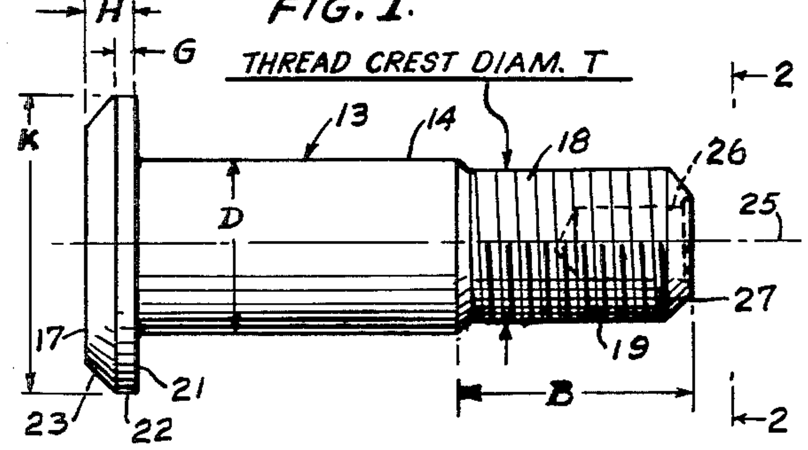
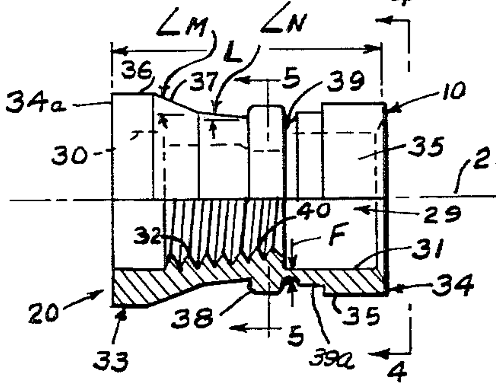
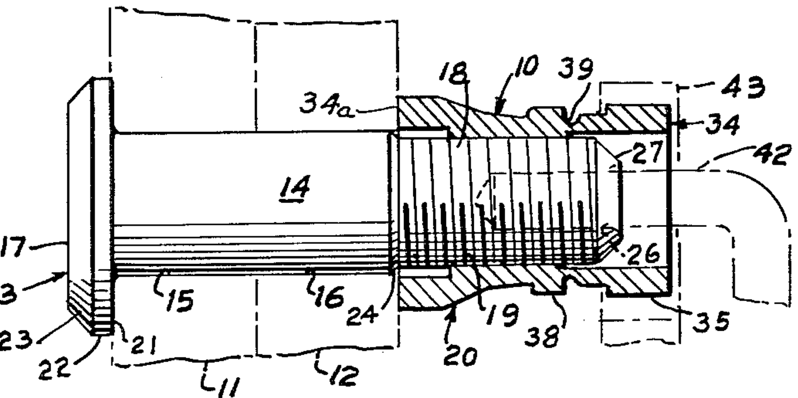
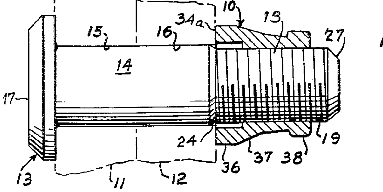
Source images (4): patent and government drawings
A patent drawing shows the patented design, which can differ in detail from today's catalog part. Each image says why it is tied to this family.
Hi-LiteLISI
Pin and collar · installed view
Sequence not shown: no public source for the intermediate stages. Installed view only.
Installed
“COLLAR WRENCHING DEVICE AUTOMATICALLY SHEARS OFF”
Hi-Shear HST10 drawing, p.sheet 1, Hi-Lite ST pin and collar after assembly ↗
Drawing traced from: After assembly view.
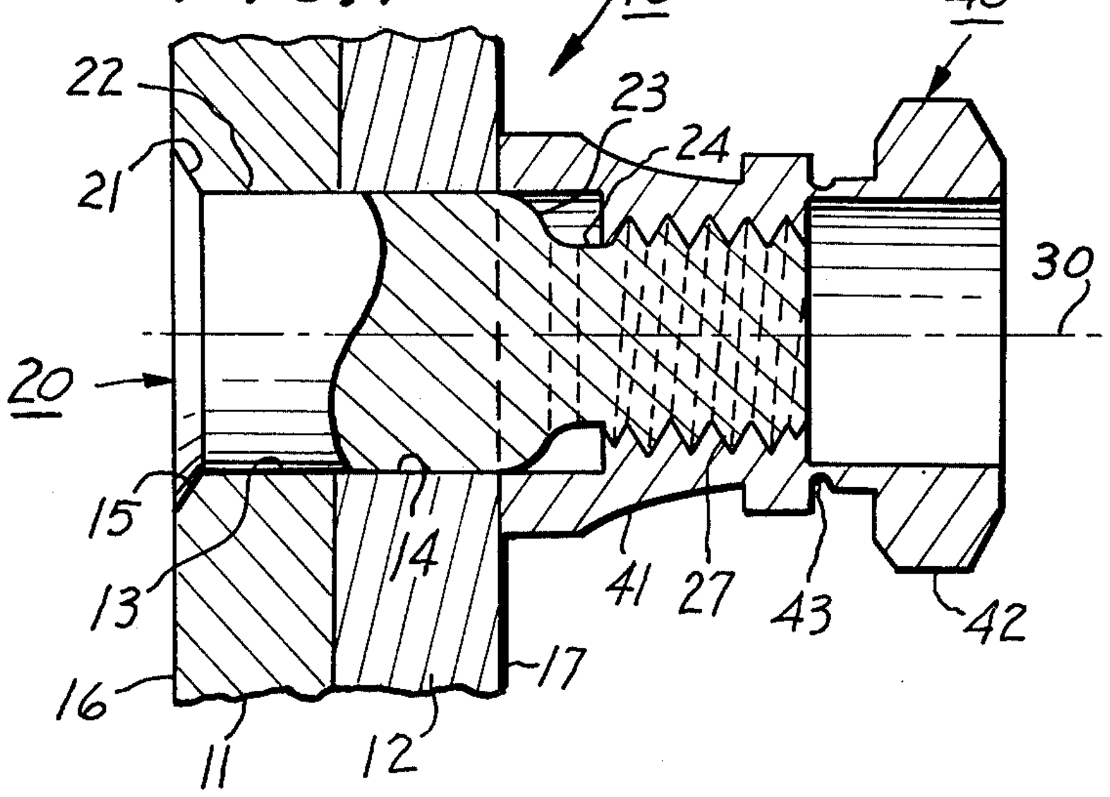
Source images (2): patent and government drawings
A patent drawing shows the patented design, which can differ in detail from today's catalog part. Each image says why it is tied to this family.
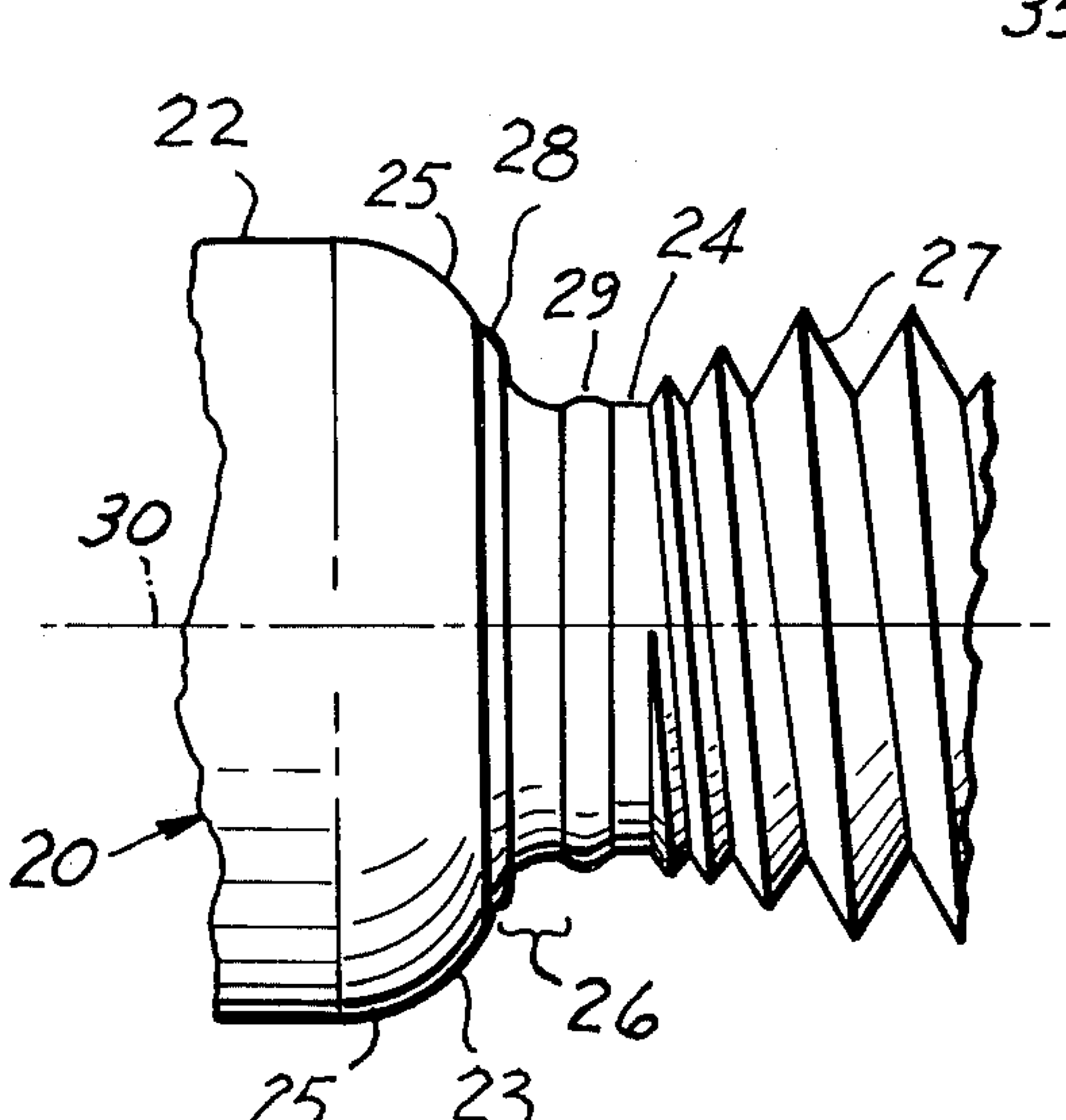
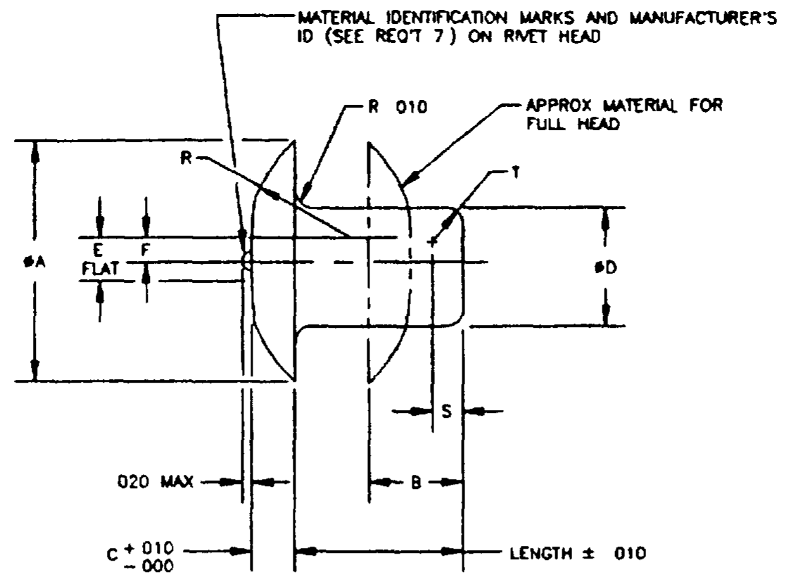
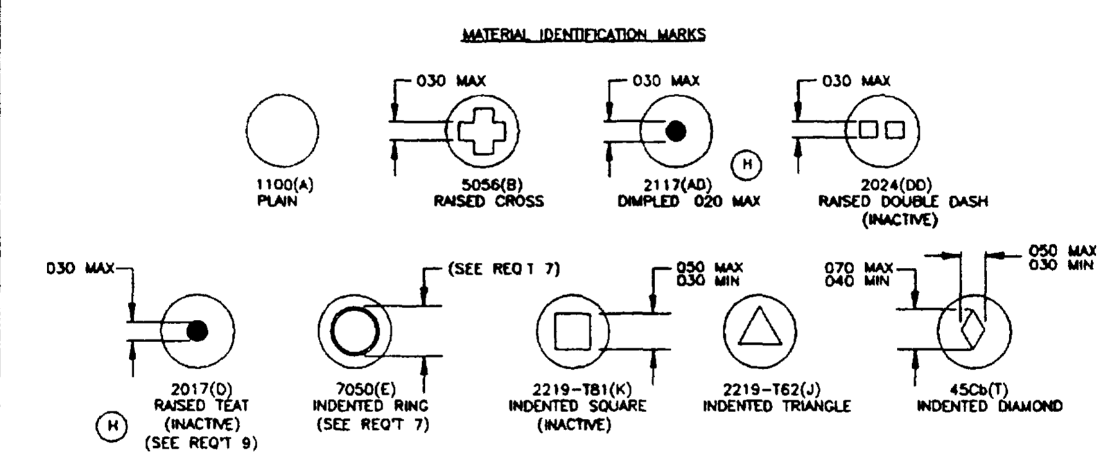
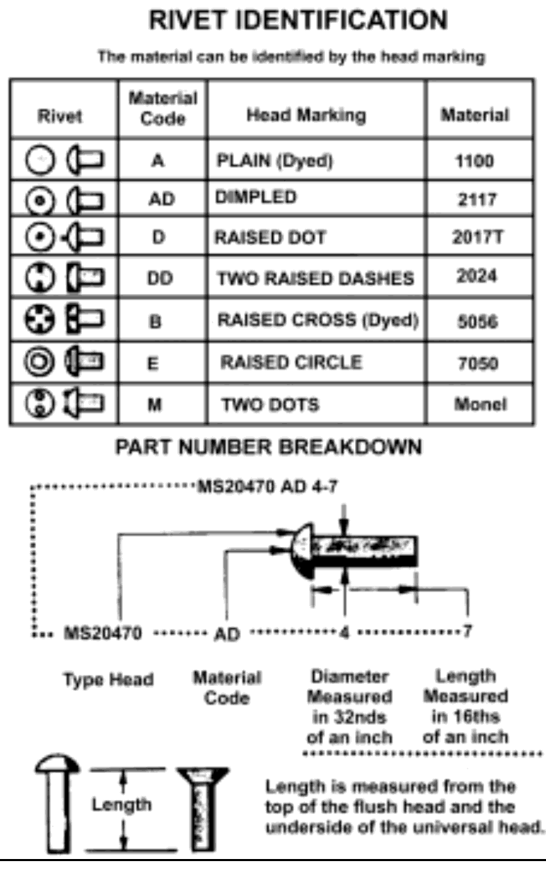
MS20470 solid rivetgeneric-NAS
Solid · 3 steps
1/3Shank protrudes
“1½D (1D MIN.)”
FAA AC 43.13-1B, p.4-21, Figure 4-6 (a) Dimensions for formed rivet heads ↗
Drawing traced from: (a), before driving.
Source images (4): patent and government drawings
A patent drawing shows the patented design, which can differ in detail from today's catalog part. Each image says why it is tied to this family.
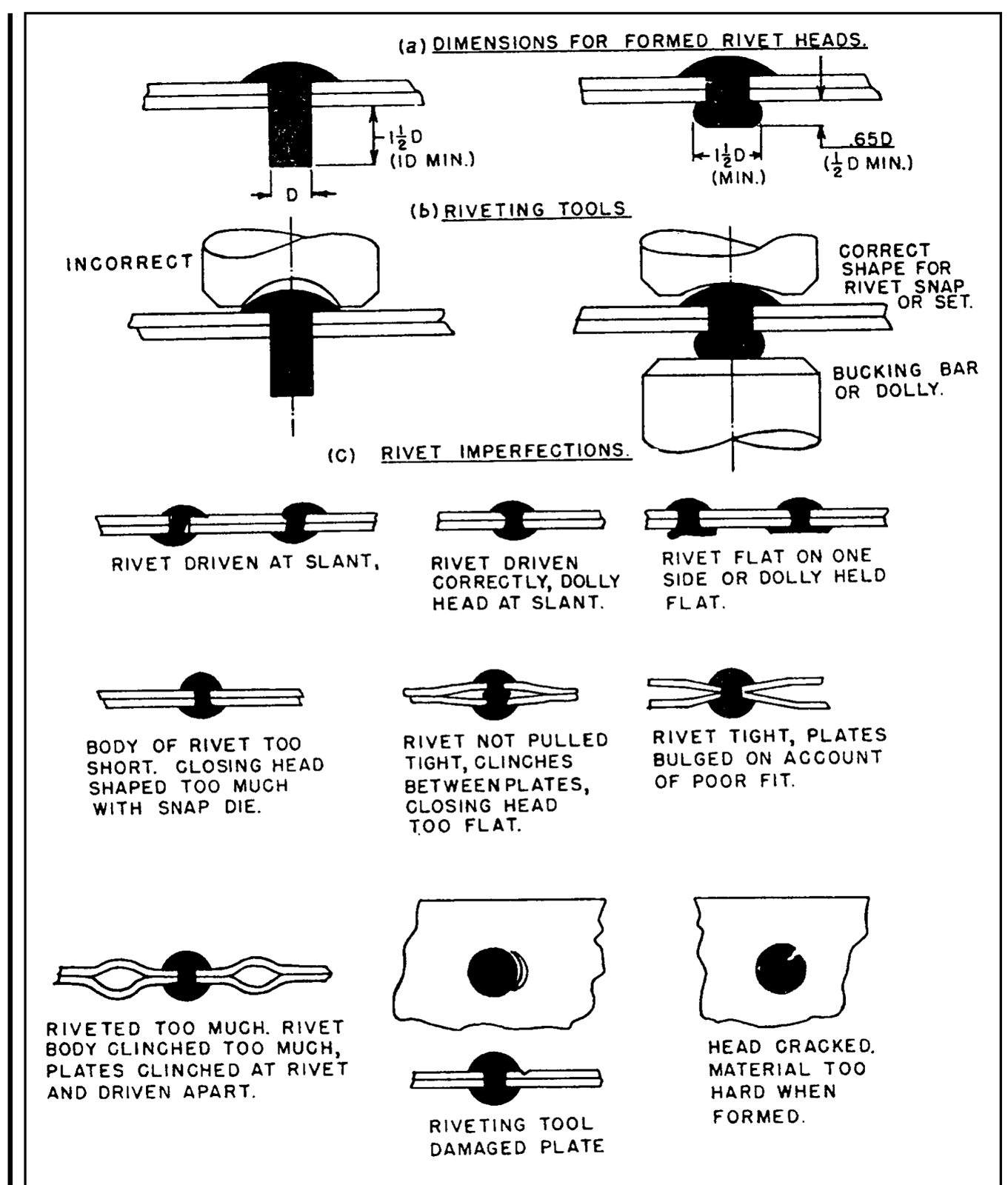
Cherry MaxiboltCherry
Pulled stem / bulbing · 3 steps
1/3Spindle pulled
“Installation shall be accomplished by the spindle being pulled into the sleeve,”
Cherry PS-CMB-7000 (Titanium MAXIBOLT), p.4 of 12, §3.4.1 ↗
Drawing traced from: Panel 1.
Source images (1): patent and government drawings
A patent drawing shows the patented design, which can differ in detail from today's catalog part. Each image says why it is tied to this family.
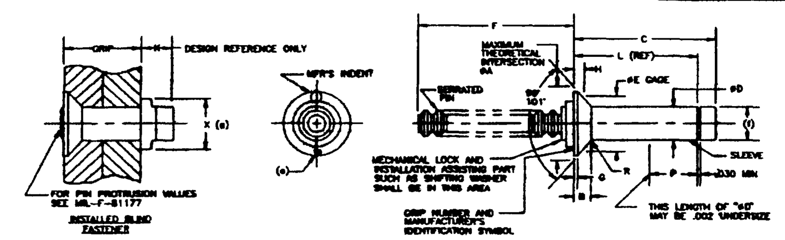
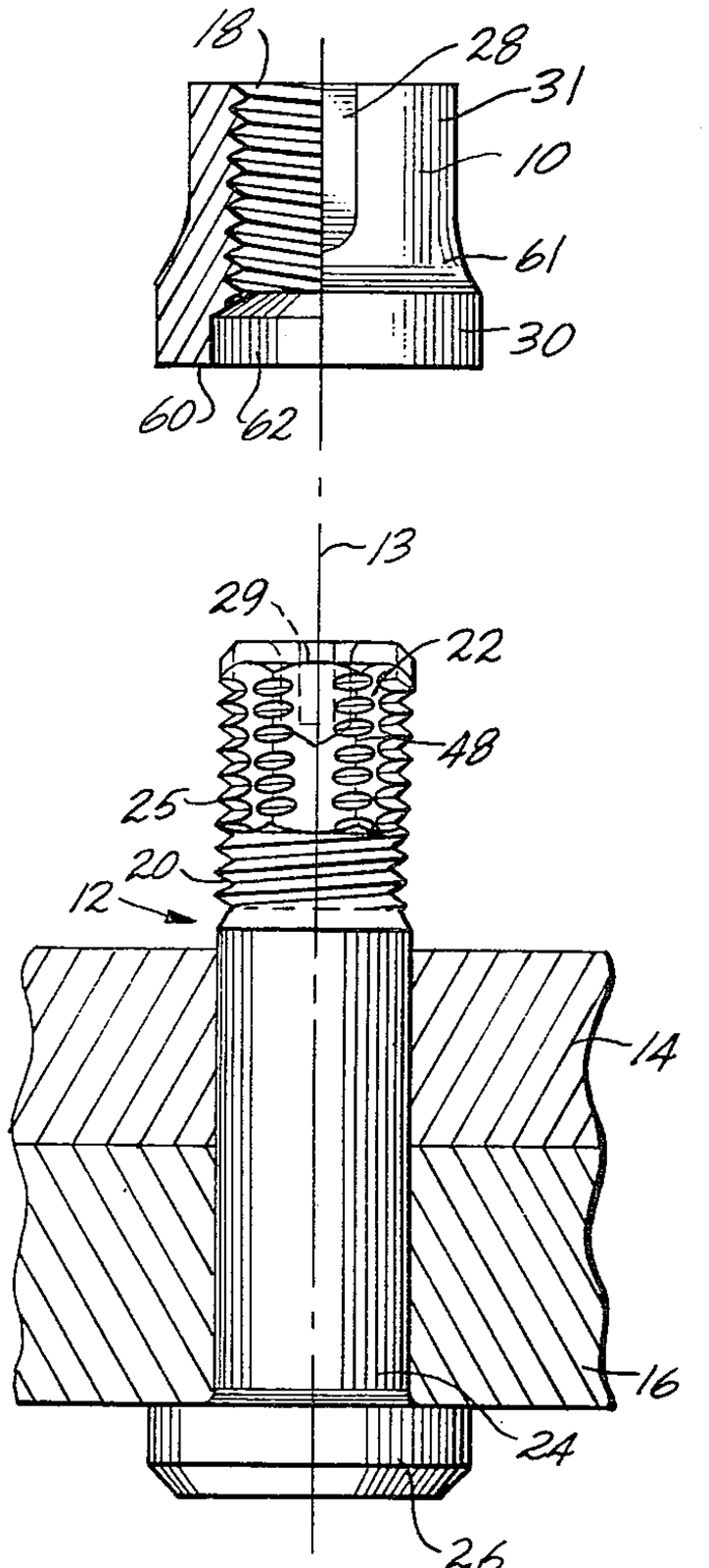
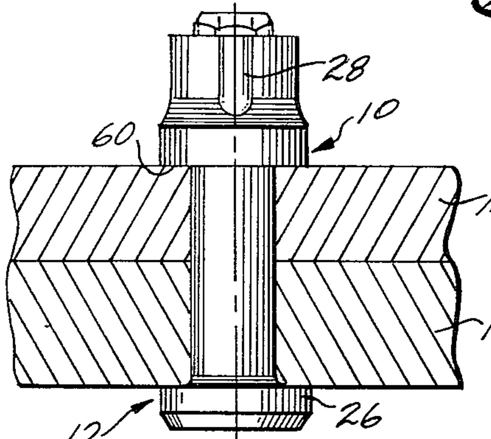
Eddie-Bolt 2Howmet/Huck
Pin and collar · 3 steps
1/3Nut started
“Hand start the nut onto the pin at least 3/4 of a turn. The nut may be spun down until it is seated on the structure.”
Howmet Eddie-Bolt 2 process manual, p.17, Installation Sequence ↗
Drawing traced from: p.17 parts figure.
Source images (5): patent and government drawings
A patent drawing shows the patented design, which can differ in detail from today's catalog part. Each image says why it is tied to this family.
Huck Magna-Lok (industrial)Howmet/Huck
Expanding sleeve · 4 steps
1/4Inserted
“Insert the fastener into the hole and slip the installation tool over the pintail.”
Howmet Huck Magna-Lok brochure, p.3, Installation Sequence ↗
Drawing traced from: Panel 1.
Cherry E-Z BuckCherry
Solid · 3 steps
1/3Inserted
“Insert rivet into hole. Measure backside protrusion. … based on a backside protrusion of 0.8D minimum and 1.5D maximum.”
Cherry CA-1032 (E-Z Buck), p.11, Rivet Grip Selection ↗
Drawing traced from: p.11 backside protrusion, 1.5D maximum.
Avdel Avdelok (industrial)Avdel
Pin and collar · 3 steps
1/3Pin and collar
“Avdel® structural lockbolts consist of a separate pin and collar which are mechanically locked during installation.”
Avdel Lockbolt Systems catalog, p.2 ↗
Drawing traced from: Panel 1.
Huck Magna-Grip (industrial)Howmet/Huck
Pin and collar · 4 steps
1/4Pin inserted, collar placed
“The fastener pin is inserted through a prepared hole. The precision collar is placed over the other end.”
Howmet Huck Magna-Grip brochure, p.3, Installation Sequence ↗
Drawing traced from: Panel 1.
Put it to work
Describe your joint and get a ranked recommendation, then open any family's page.
Open the selector →