Composi-Lok II, Monogram
MBF2121-5-100
Monogram Composi-Lok II: "high strength blind bolt for composite and metallic materials" (catalog).
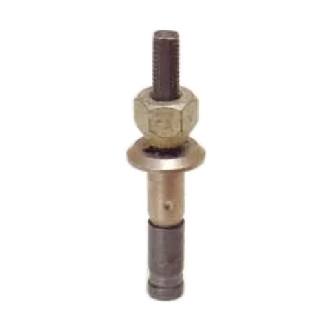
- Head Reduced protruding hex head
- Diameter 5/32" (-5)
- Grip .050-.100"
- Material A286 CRES
- Lead-time risk High
Install tool MP550BFDN-5AA, proprietary · Variable stack? Plan grips
CAD for MBF2121-5-100
| Family | Composi-Lok II (Monogram) |
|---|---|
| Head style | Reduced protruding hex head (source: Monogram drawing MBF2121 Rev U, title block, Table I, material notes) |
| Nominal diameter | 5/32" (-5) |
| Grip | max grip .100" (grip range .050-.100", MBF2121 Rev U grip table) |
| Material | A286 CRES. Nut & screw: A286; sleeve: 304 stainless steel |
Decoded from the published numbering scheme; not a claim that this exact dash number is a stocked SKU, and not a certified design authority. Always verify against the controlling drawing, spec, and your stress group.
Dimensions
| A | Head hex across flats | .250/.244 |
| D | Nut shank diameter | .1645/.1625 |
| G | Max grip + G: datum to the end of the nut shank | .017(ref) |
| H | Head height | .076/.069 |
| L | Max grip + L: datum to the end of the screw | .51(ref) |
| Recom. Hole | Drilled hole | .168/.165 |
All dimensions (19)Fewer dimensions
| B | Head diameter over the hex corners | .272min |
| E | SLEEVE and SCREW head diameter (2X) | .1640max |
| F | SCREW wrench flats, on the tail | .085/.080 |
| R | NUT head-to-shank radius | .030max |
| T | DRIVE NUT hex across flats | .375(ref) |
| Min Avail. Grip | Min available grip dash | -100 |
| J | Installed blind head diameter | .250min |
| K | Installed: blind side protrusion | .300max |
| Break-Off | Screw break-off, measured from the skin surface | +.103/-.000 |
| Tensile | Tensile structural failure, min (lbs) | 900min, lbs |
| Double Shear | Double shear, min (lbs) | 3150min, lbs |
| Locking Torque | Locking torque, min (in-lbs) | 1.0min, in-lbs |
| Grip limits | Dash 5-100 | .050-.100 |
As printed on MBF2121 Rev U sheet 1 ↗. Letters match the drawing.
Some features are scaled from the figure, not dimensioned.Scaled features
Scaled from the drawing's figure (not drawing dimensions)
| Component / feature | Scaled as | Model (in) |
|---|---|---|
| NUTnut nose diameter at its end (diameter) | 0.768 x D | .1255 |
| NUTnut nose end, from the datum | 0.162 x L - G | -.1968 |
| NUTnut bore = screw thread crest diameter (diameter) | 0.713 x D | .1166 |
| SCREWscrew thread crest diameter (threads not modelled) | 0.713 x D | .1166 |
| SLEEVEsleeve bore over the nut nose and the insert (diameter) | 0.839 x D | .1371 |
| SLEEVEsleeve bore beyond the insert (diameter) | 0.729 x D | .1192 |
| INSERTinsert outside diameter (= sleeve bore) | 0.839 x D | .1371 |
| INSERTinsert inside diameter (= sleeve bore beyond the insert) | 0.729 x D | .1192 |
| INSERTinsert end, from the datum | 0.368 x L - G | -.2982 |
| SLEEVEcrimp line (start of the crimped band), from the datum | 0.724 x L - G | -.4738 |
| SCREWscrew head top (sleeve end), from the datum | 0.826 x L - G | -.5245 |
| SCREWscrew head corner radius | 0.062 x E | .0101 |
| SLEEVEsleeve top, from the datum (where the scaled nose meets the scaled sleeve bore) | 0.112 x L - G | -.1724 |
| NUTnut nose taper (included angle) | angle, as drawn | 26.8° |
| DRIVE NUTdrive nut length | 1.064 x T | .3992 |
| DRIVE NUTdrive nut bearing diameter (cone end on the head) | 0.684 x T | .2567 |
| DRIVE NUTdrive nut bearing cone (half angle from the axis) | angle, as drawn | 30.9° |
| SCREWscrew tail beyond the drive nut | 1.056 x T | .3958 |
| SCREWwrench flats run: tail end to the drive nut (as drawn) | as drawn | .3958 |
Measured on MBF2121 Rev U sheet 1 figure at 300 dpi and kept as a ratio to a dimension this part number prints. Figure scale 596.5 px/in, fitting row -8, taken from D and E; checked against T (+0.6%), F (+1.2%), L - G (+1.1%), A (end view, across the corners: A / cos 30°) (-4.1%).
Also printed in MBF2121 Rev U for this part
| Recommended hole | .165-.168 in (MBF2121 Rev U sheet 1) |
|---|---|
| Installed blind head | J .250 in min diameter (MBF2121 Rev U sheet 1) |
| Installed protrusion | K .300 in max (TYPICAL INSTALLATION) (MBF2121 Rev U sheet 1) |
| Break-off limits | +.103 -.000 in, measured from the skin surface (MBF2121 Rev U sheet 1) |
| Tensile | 900 lbs min (structural failure) (MBF2121 Rev U sheet 1) |
| Double shear | 3150 lbs min (MBF2121 Rev U sheet 1) |
| Locking torque | 1.0 in-lbs min (MBF2121 Rev U sheet 1) |
| Min available grip | dash -100 (MBF2121 Rev U sheet 1) |
| Material and heat treat | NUT & SCREW: A286 PER THE CHEMICAL REQUIREMENTS OF AMS5731, AMS5732, AMS5734 AND AMS5737. HEAT TREATED AS REQUIRED FOR PERFORMANCE. SLEEVE: 304 STAINLESS STEEL PER AMS5639, HEAT TREATED AS REQUIRED FOR PERFORMANCE. INSERT: ACETAL PER ASTM-D4181. DRIVE NUT: MILD STEEL. (MBF2121 Rev U material and finish notes) |
| Finish | NUT, SCREW & SLEEVE: PASSIVATE PER AMS-QQ-P-35. KAL-GARD ANN-RO #1013, CONVERSION COATING OPTIONAL. INSERT: NONE. DRIVE NUT: CORROSION RESISTANT COATING COLOR BLACK. (MBF2121 Rev U material and finish notes) |
| Lubricant | DRY FILM LUBE PER MIL-L-46010 TYPE I OR EVERLUBE #812 PER MIL-L-81329, PARAFFIN WAX, OR CETYL ALCOHOL PER MIL-L-87132. (MBF2121 Rev U material and finish notes) |
Series and strength (datasheet)
MBF2110 · MBF2111 · MBF2112 · MBF2113 · MBF2120 · MBF2121 · e.g. MBF2112-6-500
Rated shear 75 KSI (catalog comparison chart, MBF2112-06-500); 3/16" (-6) double shear 4,600 lb min, tensile 1,400 lb min, all materials & head styles (MBF2003 Table 10A).
Datasheet (PDF) ↗Section from Monogram drawing MBF2121 Rev U ↗ sheet 1.Drawing notes
Model: Monogram drawing MBF2121 Rev U
Envelope model, not manufacturer CAD.Model details
MBF2121-5-100, manufacturer nominal. Simplified component model from Monogram drawing MBF2121 Rev U sheet 1. Manufacturer nominal: printed values, the mean where only two limits are printed. Flush heads hold the printed head angle; the head depth is derived. Not manufacturer CAD. Verify against the current drawing before use. One named solid per component as the drawing calls them out (NUT, SCREW, SLEEVE, INSERT and, where the drawing has one, DRIVE NUT). Features the drawing shows without a dimension are scaled from its figure and listed as scaled in the STEP header; threads are not modelled. Axis +Z, head up, z = 0 at the face the head bears on. STEP (AP214) is in inches; STL has no units and is written in millimetres.
Other head styles, same diameter and grip
- MBF2120-5-100 low profile protruding head
- MBF2113-5-100 130° flush head
MBF2121 grip chart: 5/32" (-5)
Every catalogued max-grip dash number at this diameter. Stack thickness must fall inside the fastener's grip range: see the design calculators.
Other diameters at this grip:
Threaded / torqued · 4 steps
1/4Inserted
“Insert the fastener in the hole. The Composi-Lok® II can be inserted in a properly prepared hole without interference.”
Monogram MBF2003 Rev AG (Composi-Lok II install spec), p.17, §7.2 ↗
Drawing traced from: Figure 15, left.
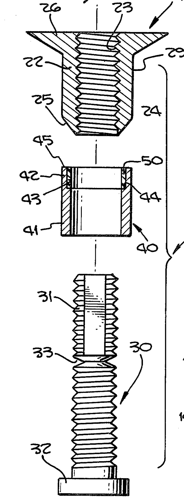
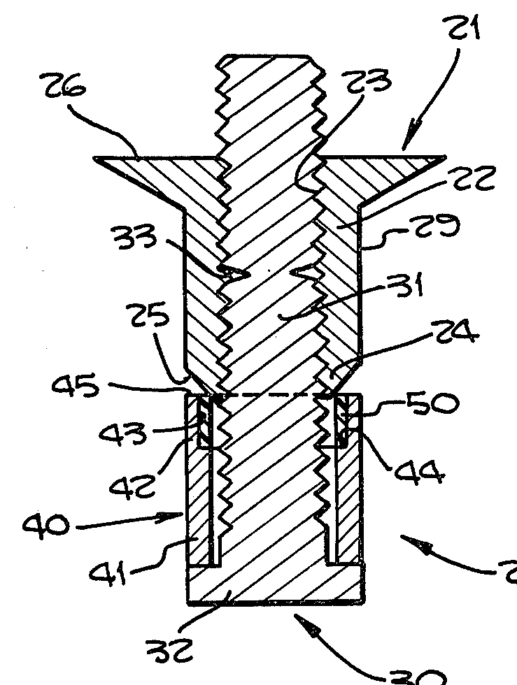
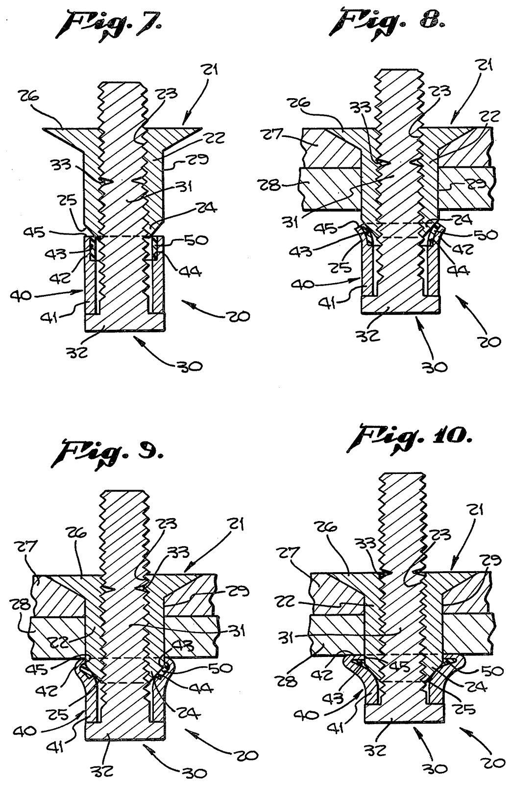
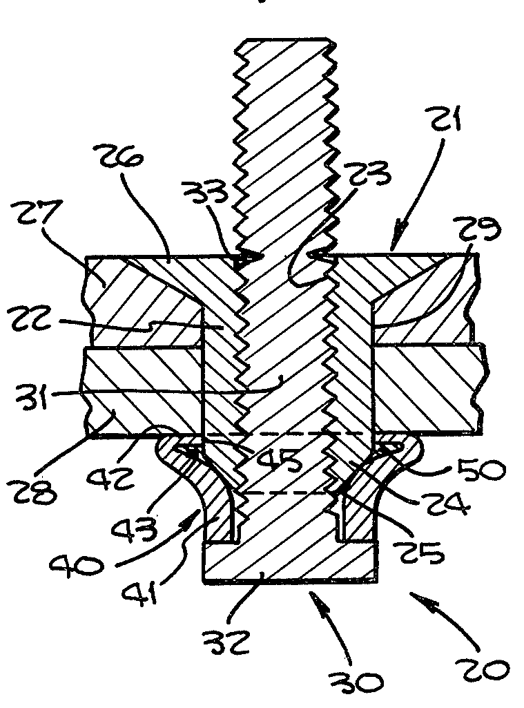
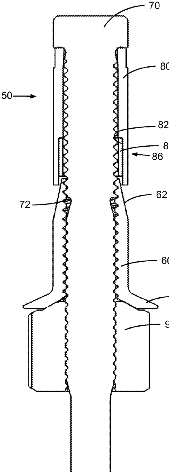
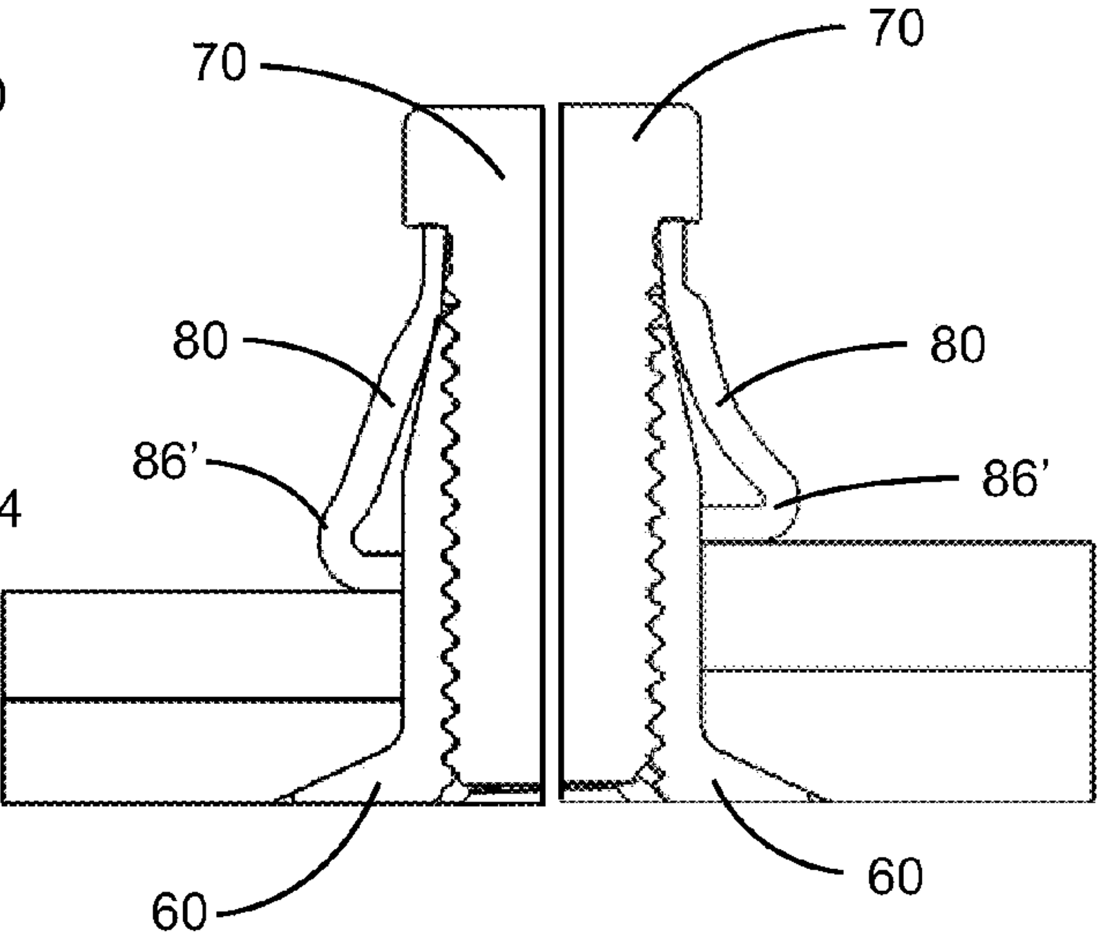
Source images (6): patent and government drawings
A patent drawing shows the patented design, which can differ in detail from today's catalog part. Each image says why it is tied to this family.
Install tooling
Install tooling: MP550BFDN-5AA (Monogram MBF2003 Rev AG (Composi-Lok II install spec), p.4, Table 1) · proprietary
- MGPCL Protruding head leaf gage (break-off check)
- RM3122-05 Removal nose piece module, protruding hex
Decode details
| Series | Composi-Lok II |
|---|---|
| Decode confidence | high |
| Numbering source | Monogram drawing MBF2121 Rev U, title block, Table I, material notes |
- Composi-Lok II grips: "incremental 0.050\" grip lengths" (MBF2003 §2.1); the grip dash is the max grip, e.g. -300 covers .250-.300" (MBF2110/2112/2113 drawings, grip table).
- Diameter dash per the drawing's basic-dimensions table (e.g. -6 = 3/16").
- Suffix "A" "designates dual drive nut system for robotic installation" (MBF2112 drawing note 1); MBF2003's installation tooling "not applicable to Composi-Lok II which have an 'A' suffix" (MBF2003 §1.1).
Government reference cross-reference (DLA FLIS)
MBF2121-5-100 is not listed in FLIS under this exact part number (FLIS data as of 2025-03-18, March 2025 snapshot). FLIS may record it with a material or finish code, or under the standard part number.
Source: DLA PUB LOG ↗. Search any part number in the decoder.
- Composi-Lok II by Monogram, blind bolt
- Datasheet (PDF) ↗
- Manufacturer page ↗
- Numbering: Monogram drawing MBF2121 Rev U, title block, Table I, material notes ↗
- Geometry: MBF2121 Rev U ↗
Lead-time risk for this family (SpecLok sourcing assessment): High
Supply signal
Supply signalfor this part number
- Not listed in FLIS under this exact part number (March 2025 snapshot).
- No SpecLok quotes yet.
A signal from records SpecLok holds, not availability, stock or a lead-time promise. FLIS lists who has recorded a part number for the item, not who makes it today. DoD awards carry no NSN or part number, so award activity is for the item name's class.
Sources: DLA FLIS Data Electronic Reading Room (PUB LOG) ↗, DLA PUB LOG ↗, USAspending.gov award search API ↗; DoD award data 2025-10-01 to 2026-07-06; compiled 2026-09-28.
Image credits: Monogram Aerospace Fasteners, Monogram Aerospace Fasteners catalog, p.4 ↗. Product images belong to their manufacturers.
Sources
- Monogram drawing MBF2121 Rev U, title block, Table I, material notes
- Monogram MBF2003 Rev AG (Composi-Lok II install spec)
- Composi-Lok II datasheet (PDF)
- Drawing MBF2112 material notes; catalog comparison chart rates MBF2112-06-500 at 75 KSI
- Drawing MBF2120 material notes; MBF2003 Table 10A strengths apply to "all materials & head styles"
- DLA PUB LOG
- DLA FLIS Data Electronic Reading Room (PUB LOG)
- USAspending.gov award search API
Next · Quote
Your quote
Get quotes above adds this part and its install tooling. The quote screen takes your email, need-by and certs.