Monogram, blind bolt
Composi-Lok II
Monogram Composi-Lok II: "high strength blind bolt for composite and metallic materials" (catalog).
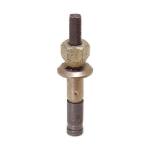
- Shear 75 ksi
- Access Blind (one-sided)
- Diameters 5/32 to 3/8"
- Materials Titanium, A286 CRES
- Lead-time risk High
Head style
Series (drawing)
Blind (one-sided), threaded blind bolt: “The wrenching part of the adapter assembly is inserted over the slabbed portion of the screw and the nose piece engages the drive-nut.” (Monogram MBF2003 Rev AG (Composi-Lok II install spec), p.17)
- Shear
- 75 ksi
- Blind bulb
- large
- Install
- One-side install
- Diameters
- 5/32, 3/16, 1/4, 5/16, 3/8"
- Lead-time risk (SpecLok assessment)
- High
Typical applications
- ·Composite and metallic structure (Monogram catalog: "for composite and metallic materials")
- ·Blind attachments to composite substructure (MIL-HDBK-17-3F C-32: large blind-side footprint, Ti or A286)
Strengths
- +Large blind side upset (Monogram catalog)
- +Controlled clamp-up: 560 lb min preload at 3/16" (40% of min UTS, catalog chart)
- +Approved on virtually all composite airframe programs (Monogram catalog)
Trade-offs
- −Monogram installation tooling (MBF2003 §3)
Also called Composilok, Composi-Lok 3, MBF series. P/N: MBF2110 · MBF2111 · MBF2112 · MBF2113 · MBF2120 · MBF2121 · e.g. MBF2112-6-500
Dimensions
| A | Head diameter | .416/.396 |
| D | Nut shank diameter | .1985/.1965 |
| G | Max grip + G: datum to the end of the nut shank | .027(ref) |
| H | Head height | .070/.063 |
| L | Max grip + L: datum to the end of the screw | .575(ref) |
| Recom. Hole | Drilled hole | .202/.199 |
All dimensions (19)Fewer dimensions
| E | SLEEVE and SCREW head diameter (2X) | .1985max |
| F | SCREW wrench flats, on the tail | .113/.108 |
| R | NUT head-to-shank radius | .030max |
| T | DRIVE NUT hex across flats | .375(ref) |
| Z | Height of the cylindrical head edge | .030max |
| Min Avail. Grip | Min available grip dash | -100 |
| J | Installed blind head diameter | .300min |
| K | Installed: blind side protrusion | .350max |
| Break-Off | Screw break-off, measured from the skin surface | +.103/-.000⑤ |
| Tensile | Tensile structural failure, min (lbs) | 1400min, lbs |
| Double Shear | Double shear, min (lbs) | 4600min, lbs |
| Locking Torque | Locking torque, min (in-lbs) | 1.5min, in-lbs |
| Grip limits | Dash 6-250 | .200-.250 |
As printed on MBF2110 Rev AB sheet 1 ↗. Letters match the drawing.
Some features are scaled from the figure, not dimensioned.Scaled features
Scaled from the drawing's figure (not drawing dimensions)
| Component / feature | Scaled as | Model (in) |
|---|---|---|
| NUTnut nose diameter at its end (diameter) | 0.768 x D | .1516 |
| NUTnut nose end, from the datum | 0.162 x L - G | -.3658 |
| NUTnut bore = screw thread crest diameter (diameter) | 0.713 x D | .1408 |
| SCREWscrew thread crest diameter (threads not modelled) | 0.713 x D | .1408 |
| SLEEVEsleeve bore over the nut nose and the insert (diameter) | 0.839 x D | .1656 |
| SLEEVEsleeve bore beyond the insert (diameter) | 0.729 x D | .1440 |
| INSERTinsert outside diameter (= sleeve bore) | 0.839 x D | .1656 |
| INSERTinsert inside diameter (= sleeve bore beyond the insert) | 0.729 x D | .1440 |
| INSERTinsert end, from the datum | 0.368 x L - G | -.4784 |
| SLEEVEcrimp line (start of the crimped band), from the datum | 0.724 x L - G | -.6736 |
| SCREWscrew head top (sleeve end), from the datum | 0.826 x L - G | -.7299 |
| SCREWscrew head corner radius | 0.062 x E | .0122 |
| SLEEVEsleeve top, from the datum (where the scaled nose meets the scaled sleeve bore) | 0.112 x L - G | -.3386 |
| NUTnut nose taper (included angle) | angle, as drawn | 29.0° |
| DRIVE NUTdrive nut length | 1.064 x T | .3992 |
| DRIVE NUTdrive nut bearing diameter (cone end on the head) | 0.684 x T | .2567 |
| DRIVE NUTdrive nut bearing cone (half angle from the axis) | angle, as drawn | 30.6° |
| SCREWscrew tail beyond the drive nut | 1.073 x T | .4025 |
| SCREWwrench flats run: tail end to the drive nut (as drawn) | as drawn | .4025 |
| NUThead chamfer above the Z edge (angle from the axis) | angle, as drawn | 44.5° |
Measured on MBF2110 Rev AB sheet 1 figure at 300 dpi and kept as a ratio to a dimension this part number prints. Figure scale 591.5 px/in, fitting row -8, taken from A and E; checked against D (+1.4%), T (+1.4%), F (+3.4%), L - G (+2.0%).
Printed in MBF2110 Rev AB for MBF2110-6-250
| Recommended hole | .199-.202 in (MBF2110 Rev AB sheet 1) |
|---|---|
| Installed blind head | J .300 in min diameter (MBF2110 Rev AB sheet 1) |
| Installed protrusion | K .350 in max (TYPICAL INSTALLATION) (MBF2110 Rev AB sheet 1) |
| Break-off limits | +.103 -.000 in, measured from the skin surface (MBF2110 Rev AB sheet 1) |
| Tensile | 1400 lbs min (structural failure) (MBF2110 Rev AB sheet 1) |
| Double shear | 4600 lbs min (MBF2110 Rev AB sheet 1) |
| Locking torque | 1.5 in-lbs min (MBF2110 Rev AB sheet 1) |
| Min available grip | dash -100 (MBF2110 Rev AB sheet 1) |
| Material and heat treat | NUT: 6Al-4V TITANIUM ALLOY PER AMS-T-9047 STA OR AMS4928 OR AMS4967 HEAT TREATED PER AMS-H-81200 TO 95 KSI SHEAR STRENGTH MINIMUM. MAXIMUM HYDROGEN CONTENT 125 PPM. SCREW: A286 CRES PER AMS5731, AMS5732 OR AMS5737 HEAT TREATED TO 175 KSI TENSILE MINIMUM. SLEEVE: 304 CRES PER AMS5639, FULLY ANNEALED. INSERT: ACETAL PER ASTM-D6778 DRIVE NUT: MILD STEEL (MBF2110 Rev AB material and finish notes) |
| Finish | ( - ) NUT: KAL-GARD ANN-RO #1012 CONVERSION COATING OR PHOSPHATE FLOURIDE PER MONOGRAM SPECIFICATION PS741, MAY BE USED AT MANUFACTURER'S OPTION. SLEEVE AND SCREW: PASSIVATE PER AMS2700, KAL-GARD ANN-RO #1013 CONVERSION COATING OPTIONAL. INSERT: NONE DRIVE NUT: COLOR GRAY (MBF2110 Rev AB material and finish notes) |
| Lubricant | SOLID FILM LUBRICANT PER AS5272 TYPE I OR TYPE II. PARAFFIN WAX, OR CETYL ALCOHOL PER AS87132 (AS REQUIRED FOR PERFORMANCE). (SEE FINISH CODE FOR ADDITIONAL RESTRICTIONS). (MBF2110 Rev AB material and finish notes) |
Datasheet strength: Rated shear 75 KSI (catalog comparison chart, MBF2112-06-500); 3/16" (-6) double shear 4,600 lb min, tensile 1,400 lb min, all materials & head styles (MBF2003 Table 10A).
Standards
- Monogram MBF series (install spec MBF2003)
Materials and galvanic compatibility vs CFRP
| Alloy | Shear (ksi) | vs CFRP | Notes | Source |
|---|---|---|---|---|
| Titanium | 75 | low | Titanium versions (MBF211x): nut 6Al-4V titanium alloy; screw A286 CRES; sleeve 304 CRES | Drawing MBF2112 material notes; catalog comparison chart rates MBF2112-06-500 at 75 KSI |
| A286 CRES | 75 | low | A286 CRES versions (MBF212x): nut & screw A286; sleeve 304 stainless steel | Drawing MBF2120 material notes; MBF2003 Table 10A strengths apply to "all materials & head styles" |
vs CFRP: MIL-STD-889C Table I, graphite column: high = incompatible in all environments; low = compatible except sea-water immersion; unrated = SpecLok has not read a rating for this material.About derived ksi
Specs source: Monogram MBF2003 (Composi-Lok II install & inspection spec) ↗: §2.1 sizes 5/32"-3/8", 0.050" grips; Table 10A strength; Table 11 hole, footprint, break-off. Materials & 75 ksi rating: Monogram catalog comparison chart. Lead-time risk is SpecLok's sourcing assessment, not a datasheet value.
Section from Monogram drawing MBF2110 Rev AB ↗ sheet 1.Drawing notes
Model
Envelope model, not manufacturer CAD. Download STEP or STL from the part panel at the top.Model details
MBF2110-6-250, manufacturer nominal. Simplified component model from Monogram drawing MBF2110 Rev AB sheet 1. Manufacturer nominal: printed values, the mean where only two limits are printed. Flush heads hold the printed head angle; the head depth is derived. Not manufacturer CAD. Verify against the current drawing before use. One named solid per component as the drawing calls them out (NUT, SCREW, SLEEVE, INSERT and, where the drawing has one, DRIVE NUT). Features the drawing shows without a dimension are scaled from its figure and listed as scaled in the STEP header; threads are not modelled. Axis +Z, head up, z = 0 at the face the head bears on. STEP (AP214) is in inches; STL has no units and is written in millimetres.
Source
- MBF2110 Rev AB ↗ blind fastener, low profile protruding head for advanced composite materials titanium, ECN date 08/24/13.
- High break-off ("H", break-off +.153/+.050; MBF2110 note 5, e.g. MBF2110( )-6H200). Same geometry.
- Every head style, rivet number, diameter and grip on the transcribed standards pages. The 3D view, the drawing and the STEP / STL download are all built from the printed dimension letters; nothing the catalog does not dimension is modelled.
Monogram MBF drawings p.1-2, manufacturer printed values.
Printed as is: 19 values in Monogram MBF drawings that look inconsistent
- p.2 MBF2110 Rev AB sheet 2, Table III: Oversize -6.5 and -8.5 print ØE MAX (.2141, .2751) one ten-thousandth above the ØD upper limit (.2140, .2750); in Table I ØE MAX never exceeds the ØD upper limit.
- p.1 MBF2111 Rev AC sheet 1, Table I and Table I (continued): Note 1 places a special finish code "( )" directly after MBF2111 (drawing number "MBF2111( )-( )-( )( )", Table II and Table III part numbers "MBF2111( )-..."), but the Table I part-number cells print "MBF2111-5-( )" without that slot.
- p.2 MBF2112 Rev AF sheet 2, note 8: Note 8 reads "STANDARD GRIP LENGTHS ARE SHOWN IN TABLE III"; the grip table on the sheet is TABLE IV (Table III is the oversize table).
- p.1 MBF2113 Rev AL sheet 1, Table I, (L) column: The (L) cell .575 is printed as one cell merged across the MBF2113-5.5-( ) and MBF2113-6-( ) rows, so -5.5 reads L = .575, the same as -6, while every other merged cell in Table I pairs a nominal dash with the oversize dash below it (-5/-5.5, -6/-6.5, -8/-8.5). MBF2112 Rev AF prints L = .544 for its -5.5. Kept as printed (.575 in both rows).
- p.1 MBF2120 Rev U sheet 1, first dimension table, row -8: The part number cell prints "MBF2120-8( )" without the dash before "( )"; every other row, and the -8 row of the second table, print "-8-( )".
- p.1 MBF2120 Rev U sheet 1, first dimension table, row -7: The mm conversion of the ØA upper limit .421 prints 10,093; the -6 row prints 10,693 for the same .421 (.421 in = 10,693 mm).
- p.1 MBF2120 Rev U sheet 1, dimension tables; sheet 2 grip table: No table on the drawing carries a table number or title; the grip table is headed only GRIP RANGE and note 1 does not reference it.
- p.1 MBF2121 Rev U sheet 1, end view and dimension table: The end view draws A between the two corner points (dotted) of the nut head hex, i.e. across corners, and shows no ØB. The table cannot be read that way: A .250/.244 lies below ØB MIN. .272 for -5 (and likewise for every size), so A is the hex across flats and ØB the diameter over the corners, as on MBF2111, whose figure labels A HEX ACROSS FLATS.
- p.1 MBF2121 Rev U sheet 1, lower table, LOCKING TORQUE MIN.: MBF2121-12-( ) prints 4.5 IN-LBS with 0,452 N-m; 0,452 is the conversion of 4.0 (printed for -11). 4.5 in-lbs is 0,508 N-m (as printed on MBF2111).
- p.2 MBF2121 Rev U sheet 2, notes 1 and 3: Note 3 example "MBF2121-06-H800" prints the diameter dash as "06" while note 1 and the tables print "6"; the "H" is prefixed to the grip dash (bracket under "H800"), keeping both dashes.
- p.2 MBF2121 Rev U sheet 2, note 1 and robotic table: The robotic part numbers "MBF2121( )-5-( )A" carry a "( )" slot after MBF2121 that neither note 1 ("MBF2121 - 6 - 100 ( )"), the drawing number "MBF2121-( )-( )( )" nor the sheet 1 part numbers "MBF2121-5-( )" have, and no note defines it.
- p.1 MBF2013 Rev AG sheet 1, dimension table, D column (mm): MBF2013-6-( ) D lower limit .1965 in. is printed with the mm conversion 5,000; .1965 in. is 4,991 mm (MBF2113 Rev AL prints 4,991 for the same limit). Inch value kept as printed; mm columns are not transcribed.
- p.2 MBF3005 Rev AB sheet 2, note 1: Note 1 reads "DESIGNATES GRIP (TABLE III)"; the grip table on the sheet is TABLE IV and no Table III is printed.
- p.1 MBF3005 Rev AB sheet 1, figure: The "DISTORTION OF ØD PERMISSIBLE IN LOCKING AREA" callout carries flag ⑥; the distortion note is note 5 (note 6 is head markings, also flagged ⑥ on the end view).
- p.2 MBF3005 Rev AB sheet 2, Table II and robotic figure: Table II is flagged ⑧ and its TOL. C heading and the robotic figure are flagged ⑦, but the general notes end at note 6.
- p.1 MBF3005 Rev AB sheet 1, Table I: Table I heads the R column "R RAD" with two stacked limits; the figure callout reads "R RAD MAX".
- p.2 MBF3006 Rev AB sheet 2, note 1: Note 1 reads "DESIGNATES GRIP (TABLE III)"; the grip table on the sheet is TABLE IV and no Table II or Table III is printed.
- p.1 MBF3006 Rev AB sheet 1, Table I: (H) is .075 at -10 and .074 at -11, the only diameter step where the reference head height falls while (ØA) grows (.635/.626 to .666/.657, S MAX .014 to .015).
- p.1 MBF3006 Rev AB sheet 1, Table I: Table I heads the R column "R RAD" with two stacked limits; the figure callout reads "R RAD MAX".
7 head styles
Some variants only partly sourcedDrawn from the -6 (3/16") row: A (head dia), H (head height), D .1965-.1985. Monogram drawing MBF2110 Rev AB, Table I, MBF2110-6 ↗
Low profile protruding head
- MBF2110 Composi-Lok II: Titanium. Nut: 6Al-4V titanium alloy; screw: A286 CRES; sleeve: 304 CRES-5 to -12; oversize -5.5, -6.5, -8.5 (Table III). Grip dash = max grip, .050" steps, -100 to -1700 (Table IV); min available grip -100 (-5 to -9), -150 (-10 to -12).Monogram drawing MBF2110 Rev AB, title block, Tables I, III, IV, material notes ↗
- MBF2120 Composi-Lok II: A286 CRES. Nut & screw: A286; sleeve: 304 stainless steel-5 to -12. Grip dash = max grip, .050" steps, -100 to -1700 (Table IV); min available grip -100 (-5 to -7), -150 (-8 to -12).Monogram drawing MBF2120 Rev U, title block, Table I, material notes ↗
- MBF3003 Composi-Lok IIa: Titanium. Nut: 6Al-4V titanium alloy; screw: A286 CRES; sleeve: 304 stainless steel-5 to -12, similar to MBF2110 except "IMPROVED OUT-OF-GRIP FLAGGING CAPABILITY", "INCREASED BLIND SIDE PROTRUSION BEFORE AND AFTER UPSET" and "INCREASED INSTALLED WEIGHT" (drawing note 4). Grip dash = max grip, .050" steps, -100 to -1150 (Table II); min available grip -100 (-5 to -9), -150 (-10 to -12).Monogram drawing MBF3003 Rev V, title block, Tables I, II, note 4, material notes ↗
Head-specific tooling
- MGPCL Protruding head leaf gage (break-off check) (Monogram MBF2003 Rev AG, Table 13 (inspection gages) ↗)
- RM3118-( ) Removal nose piece module, flush head style: "Use flush head style nose piece modules for non-hexagonal protruding head fasteners (e.g. MBF2110 and MBF2120)" (Monogram MBF2003 Rev AG, Figure 9 / Table 9 (removal), note 5 ↗)
MBF2122 and MBF2123 are listed with the flush heads in MBF2003 (Tables 11 and 13), and the Composi-Lok 3 bases MBF2312, MBF2313, MBF2315 and MBF2334 in the MBF2301 tool tables, but their product drawings are not public, so their head angle and material are not shown.
Head styles (manufacturer terms)
- Low profile protruding head (MBF2110, MBF2120, MBF3003)
- Reduced protruding hex head (MBF2111, MBF2121, MBF3004)
- 100° flush head (MBF2112, MBF3005)
- 130° flush head (MBF2113, MBF2013, MBF3006)
- Flush head (MBF2003 Table 11 group; angle not decoded) (MBF2122, MBF2123)
- Protruding head (MBF2310)
- Flush head (MBF2301 figure; angle not decoded) (MBF2312, MBF2313, MBF2315, MBF2334)
Threaded / torqued · 4 steps
1/4Inserted
“Insert the fastener in the hole. The Composi-Lok® II can be inserted in a properly prepared hole without interference.”
Monogram MBF2003 Rev AG (Composi-Lok II install spec), p.17, §7.2 ↗
Drawing traced from: Figure 15, left.
Source images (6): patent and government drawings
A patent drawing shows the patented design, which can differ in detail from today's catalog part. Each image says why it is tied to this family.
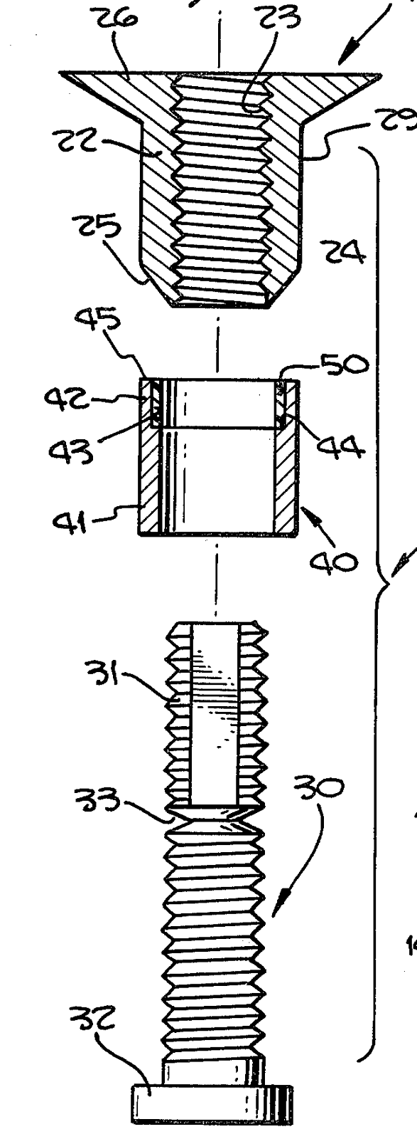
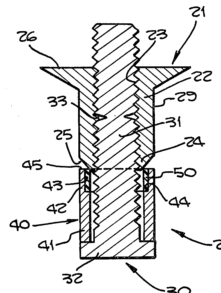
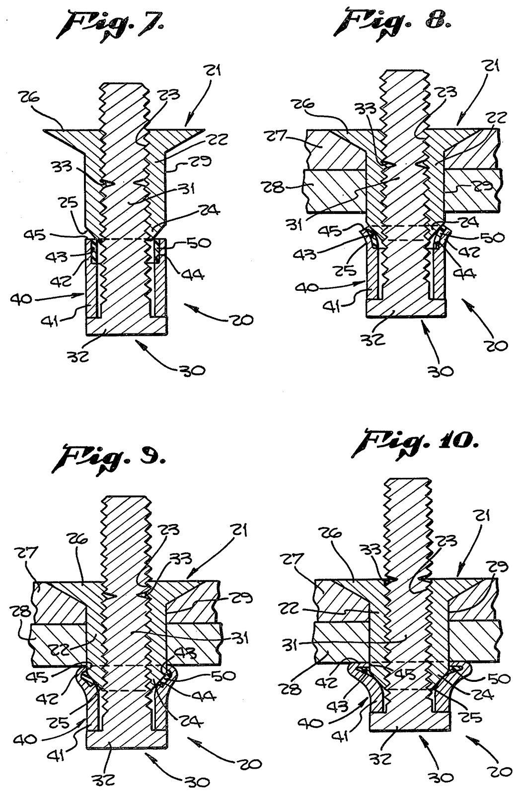
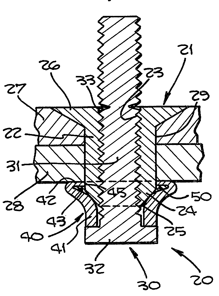
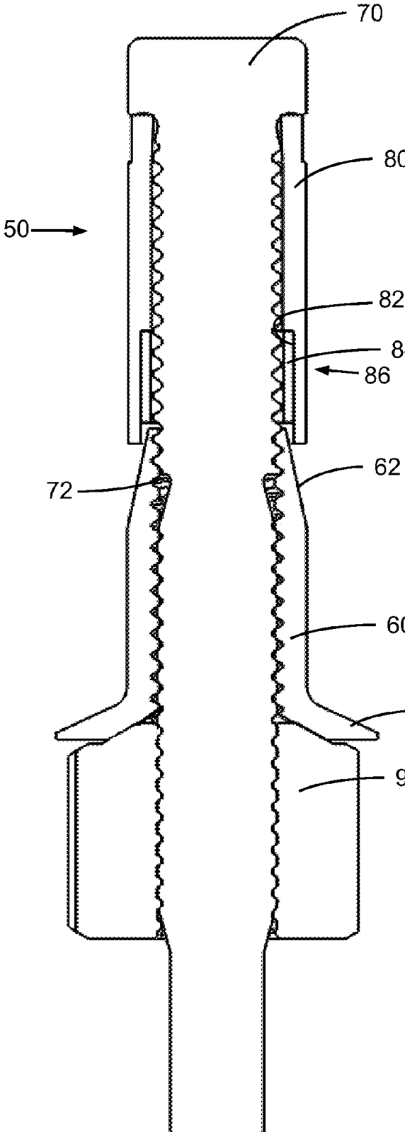
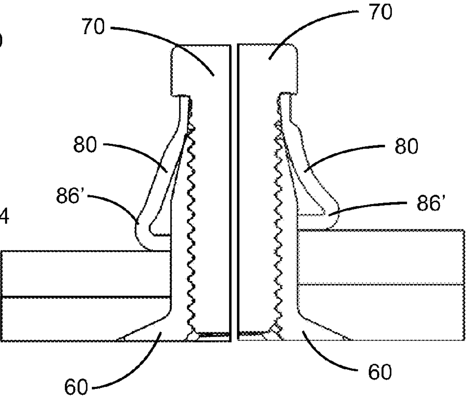
Official manufacturer install demonstration: Composi-Lok II installation.
Installation verification and preload
Installed preload
- Composi-Lok II 3/16" (MBF2112-06-500), preload: 560 minimum required (40% of min UTS) · 1,000 typical, pounds (Monogram catalog comparison chart)
- Composi-Lok 3 3/16" (MBF2312-06-500), preload: 560 minimum required (40% of min UTS); typical "anticipated to be equal to those of Composi-Lok II" (catalog chart, note 2)
MBF2003 publishes no preload figure. It offers an optional indirect check: "If desired, clamp-up may be determined indirectly be seating torque"; resisting rotation at the Table 12 values (-5: 4 to -12: 30 in.-lb minimum, counter-clockwise, via the MHTFDN torque adaptor) "is a good indication that the required preload has been imparted to the joint" (MBF2003 §10.2). "Care should be taken not to exceed the seating torque."
What to check after install
- "The stem break-off position of the screw in the head of the nut is a positive indication that the fastener has been properly installed (provided that the correct grip length has been used)" (MBF2003 §10.1). Corebolt break-off limits +0.103"/-0.000", measured from the skin surface on protruding head fasteners and from the head of the fastener on flush style fasteners (MBF2003 Table 11 note 4); "Product drawings list the acceptable stem break-off limits" (§10.1).
- Break-off out of limits "may indicate the use of the wrong grip fastener or other problem. In either case, the fastener should be removed, the grip length carefully check, and then replaced by the correct grip fastener, as necessary" (MBF2003 §10.1).
- Optional seating-torque check ("if desired"): the fastener resists counter-clockwise rotation at the Table 12 minimum for its size, -6: 6 in.-lb (MBF2003 §10.2).
- Composi-Lok 3 differs: it "is designed to provide a flush break throughout the fastener's grip accommodation. For this reason the stem break-off position of the screw in the head of the nut is NOT an indicator that the fastener has been properly installed" (MBF2301 §9.1). Break-off limits +.000/-.030 for -5 and -6, larger sizes T.B.D. (MBF2301 Table 11). Optional seating torque 25 in.-lb minimum (-5 to -7), 50 (-8 to -12) (MBF2301 Table 12).
- "The corebolt protrusion may be shaved flush with the sheet surface using a standard rivet shaver equipped with a carbide cutter" at "approximately 10,000 RPM" (MBF2003 §9.1).
Check gauges (3) and sources.Details
- Flush head barrel gage MGFCL-5 through MGFCL-12 (MBF 2112, 2113, 2122, 2123); protruding head leaf gage MGPCL (MBF 2110, 2111, 2120, 2121) (MBF2003 Table 13). Gage prongs straddle the screw: high break-off check, gage must not rock; low break-off check, gage must rock (MBF2003 Figure 16).
- Composi-Lok grip gage BFS-1 and grip scale slide GSS-1, available as an assembly, BFS-1A (MBF2003 Figure 12). Measures grip before installation: "the grip length should be checked with a grip gauge" (§6.1).
- Torque adaptor MHTFDN -5 through -12 for the seating torque check (MBF2003 Table 12).
Sources: MBF2003 installation spec · Monogram catalog (preload chart) · MBF2301 (Composi-Lok 3). Acceptance limits belong to the controlling spec; verify against your program's process documentation.
- Tool
- Monogram pneumatic and hand installation tools (MBF2003 §3, Figures 1-7, e.g. MP550BF pneumatic pistol)
- Special / proprietary
- Special tooling · proprietary
- Training
- Not stated in the cited documents.
- Inspection
- Corebolt break-off within +0.103"/-0.000" (MBF2003 Table 11/13) and optional seating-torque check (Table 12).
"The screw is turned as the nut is held stationary by the drive-nut ... The sleeve is compressed between the screw head and the conical end of the nut and is drawn over the tapered nose portion of the nut. The sleeve is thereby expanded subsequently forming a head against the mating surface being joined. As driving is completed, the slabbed portion of the screw is snapped off and ejected along with the drive-nut" (MBF2003 §7.4).
The published install tool and nose for each size, other access options, and the gauges that check the install, from the manufacturer's own tool tables.
| Dia. | Published tool + nose | Other access | Gauges |
|---|---|---|---|
| -5 | MP550BFDN-5AA (MP550BF + MPPBF-08 + MPBF-05) | Right angle, Close quarter | BFS-1A, MGFCL-5, MGPCL, MHTFDN-5 |
| -6 | MP550BFDN-6AA (MP550BF + MPPBF-08 + MPBF-06) | Right angle, Close quarter | BFS-1A, MGFCL-6, MGPCL, MHTFDN-6 |
| -8 | MP550BFP-8AA (MP550BF + MPPBF-08 + MPBF-08) | Right angle, Close quarter | BFS-1A, MGFCL-8, MGPCL, MHTFDN-8 |
| -10 | MP550BFDN-10AA (MP550BF + MPP-12 + MPTBF-10) | Close quarter | BFS-1A, MGFCL-10, MGPCL, MHTFDN-10 |
| -12 | MP550BFDN-12AA (MP550BF + MPP-12 + MPTBF-12) | Close quarter | BFS-1A, MGFCL-12, MGPCL, MHTFDN-12 |
Full tool tables, envelopes, clearances and source notesCompare tooling burden across all 25 families
Monogram MBF2003 Rev AG (Composi-Lok II), §8 Removal and Figure 9
- “Composi-Lok II may be removed with the tooling shown in Figure 9 of this specification. Complete kits are available from Monogram Aerospace Fasteners. Contact factory for details.” Monogram MBF2003 Rev AG (Composi-Lok II install spec), p.18, §8.1 ↗
- “Corebolt protrusion should be milled flush prior to removal.” Monogram MBF2003 Rev AG (Composi-Lok II install spec), p.12, Figure 9, Table 9 ↗
- “A complete tool consists of the air motor module (RM3197), a nose piece module (column 3) and a carbide star drill (column 4). A depth gage (column 6) is required for setting drilling depth.” Monogram MBF2003 Rev AG (Composi-Lok II install spec), p.12, Figure 9, Table 9 ↗
- “Use flush head style nose piece modules for non-hexagonal protruding head fasteners (e.g. MBF2110 and MBF2120).” Monogram MBF2003 Rev AG (Composi-Lok II install spec), p.12, Figure 9, Table 9 ↗
Cautions
- “If a fastener has been removed, the same diameter Composi-Lok II can be reinstalled provided the hole has not been damaged. In the event that the hole has been damaged, the next larger diameter Composi-Lok II should be used (NOTE: for flush head fasteners the countersink will have to be deepened).” Monogram MBF2003 Rev AG (Composi-Lok II install spec), p.14, §4.6 ↗
- “Also available as vacuum index assisted RK5000 Removal kit for removal of -5, -6 and -8 diameter Visu-Loks and Composi-Loks. Contact factory for removal of H-11 and Inconel Monogram fasteners.” Monogram MBF2003 Rev AG (Composi-Lok II install spec), p.12, Figure 9, Table 9 ↗
Removal tooling and drill sizes
| Nominal diameter | Nose piece, flush | Nose piece, protruding hex | Carbide star drill | Drill size dia. +.0000/.0005 | Depth gage |
|---|---|---|---|---|---|
| -5 (.1635) | RM3118-05 | RM3122-05 | RM3116-05 | .1540 | RM3125-01 |
| -6 (.1975) | RM3118-06 | RM3122-06 | RM3116-06 | .1890 | RM3125-01 |
| -7 (.2265) | RM3118-07 | RM3122-07 | RM3116-07 | .2180 | RM3125-01 |
| -8 (.2585) | RM3118-08 | RM3122-08 | RM3116-08 | .2500 | RM3125-01 |
| -9 (.2885) | RM3118-09 | RM3122-09 | RM3116-09 | .2810 | RM3125-02 |
| -10 (.3105) | RM3118-10 | RM3122-10 | RM3116-10 | .3020 | RM3125-02 |
| -11 (.3425) | RM3118-11 | RM3122-11 | RM3116-11 | .3320 | RM3125-02 |
| -12 (.3735) | RM3118-12 | RM3122-12 | RM3116-12 | .3590 | RM3125-02 |
Monogram MBF2003 Rev AG (Composi-Lok II install spec), p.12, Figure 9, Table 9 ↗
Also published: Monogram MBF2301 Rev NR (Composi-Lok 3), §8.0
- “Composi-Lok 3 may be removed with the tooling shown in Figure 9 of this specification. Complete kits are available from Monogram Aerospace Fasteners. Contact factory for details.” Monogram MBF2301 Rev NR (Composi-Lok 3 install spec), p.18, §8.0 ↗
- “Corebolt protrusion should be milled flush prior to removal.” Monogram MBF2301 Rev NR (Composi-Lok 3 install spec), p.12, Figure 9, RK5000 Fastener Removal Kit, note 3 ↗
Cautions
- “This kit is used to remove alloy steel, titanium and A-286 Visu-Loks or A-286 and titanium Composi-Lok fasteners. To remove H-11 and similar material, contact factory for details.” Monogram MBF2301 Rev NR (Composi-Lok 3 install spec), p.12, Figure 9, note 2 ↗
None of the removal procedures on file gives a composite-specific removal caution. The Monogram specs address composite at the hole instead: holes "reasonably round and free from burrs (metallic structure) and delamination (graphite/epoxy type structure)" (MBF2003 §5.1).
MBF2110
Diameters 5/32", 0.171875", 3/16", 0.203125", 0.21875", 1/4", 0.265625", 0.28125", 5/16", 0.34375", 3/8" · 33 grip lengths
MBF2111
Diameters 5/32", 0.171875", 3/16", 0.203125", 0.21875", 1/4", 0.265625", 0.28125", 5/16", 0.34375", 3/8" · 33 grip lengths
MBF2112
Diameters 5/32", 0.171875", 3/16", 0.203125", 0.21875", 1/4", 0.265625", 0.28125", 5/16", 0.34375", 3/8" · 32 grip lengths
MBF2113
Diameters 5/32", 0.171875", 3/16", 0.203125", 0.21875", 1/4", 0.265625", 0.28125", 5/16", 0.34375", 3/8" · 33 grip lengths
MBF2120
Diameters 5/32", 3/16", 0.21875", 1/4", 0.28125", 5/16", 0.34375", 3/8" · 33 grip lengths
MBF2121
Diameters 5/32", 3/16", 0.21875", 1/4", 0.28125", 5/16", 0.34375", 3/8" · 33 grip lengths
MBF2013
Diameters 5/32", 3/16", 0.21875", 1/4", 0.28125", 5/16", 0.34375", 3/8" · 32 grip lengths
MBF3003
Diameters 5/32", 3/16", 0.21875", 1/4", 0.28125", 5/16", 0.34375", 3/8" · 22 grip lengths
MBF3004
Diameters 5/32", 3/16", 0.21875", 1/4", 0.28125", 5/16", 0.34375", 3/8" · 33 grip lengths
MBF3005
Diameters 5/32", 3/16", 0.21875", 1/4", 0.28125", 5/16", 0.34375", 3/8" · 32 grip lengths
MBF3006
Diameters 5/32", 3/16", 0.21875", 1/4", 0.28125", 5/16", 0.34375", 3/8" · 25 grip lengths
- Manufacturer
- Monogram
- Category
- Blind bolt
- Datasheet (PDF) ↗
- Manufacturer page ↗
- Monogram MBF2003 (Composi-Lok II install & inspection spec) ↗: §2.1 sizes 5/32"-3/8", 0.050" grips; Table 10A strength; Table 11 hole, footprint, break-off. Materials & 75 ksi rating: Monogram catalog comparison chart.
- Monogram MBF drawings ↗ Drawing revisions as listed per table (archived 2016-04-04)
Find the part number for your stack
Enter your stack thickness and diameter to get the MBF2110 dash number.
Dash numbers and grips: Monogram drawing MBF2110 Rev AB, dimension tables (nominal and oversize) and grip table ↗
Sourcing
Lead-time risk (SpecLok sourcing assessment): High
Get quotes: SpecLok sources this from authorized distributors and returns price, lead time and certs.You buy from the authorized distributor, who is named on your returned quote. SpecLok is free for buyers.
Supply signalfor this family
- 895 NSNs carry a part number of this family, recorded by 23 CAGE codes (FLIS, March 2025).
- Last DoD award for RIVET,BLIND items (FSC 5320): 2026-06-26; 3,082 awards since 2025-10-01.
- No SpecLok quotes yet.
A signal from records SpecLok holds, not availability, stock or a lead-time promise. FLIS lists who has recorded a part number for the item, not who makes it today. DoD awards carry no NSN or part number, so award activity is for the item name's class.
Sources: DLA FLIS Data Electronic Reading Room (PUB LOG) ↗, DLA PUB LOG ↗, USAspending.gov award search API ↗; DoD award data 2025-10-01 to 2026-07-06; compiled 2026-09-28.
Image credits: Monogram Aerospace Fasteners, Monogram Aerospace Fasteners catalog, p.4 ↗. Product images belong to their manufacturers.
Sources
- Monogram MBF2003 Rev AG (Composi-Lok II install spec)
- Composi-Lok II datasheet (PDF)
- Monogram product page
- Composi-Lok II installation video
- Monogram drawing MBF2110 Rev AB
- Monogram drawing MBF2120 Rev U
- Monogram drawing MBF3003 Rev V
- Monogram drawing MBF2111 Rev AC
- Monogram drawing MBF2121 Rev U
- Monogram drawing MBF3004 Rev U
- Monogram drawing MBF2112 Rev AF
- Monogram drawing MBF3005 Rev AB
- Monogram drawing MBF2113 Rev AL
- Monogram drawing MBF2013 Rev AG
- Monogram drawing MBF3006 Rev AB
- Monogram MBF2301 Rev NR (Composi-Lok 3 spec)
- MIL-STD-889C Table I, graphite column: high = incompatible in all environments; low = compatible except sea-water immersion; unrated = SpecLok has not read a rating for this material.
- Monogram catalog (preload chart)
- DLA FLIS Data Electronic Reading Room (PUB LOG)
- DLA PUB LOG
- USAspending.gov award search API
- AFT, Composi-Lok / Visu-Lok tooling guide
Next · Find
Find your part number
Several zones or a variable bondline? The grip planner splits the buy across grips; then get it quoted.